What this system does
The signage helps a person in the building understand where they are, where they need to go, and how to get there — without first having to learn how the building works.
Navigation is led by what a visitor is actually looking for: destinations, the essential services such as washrooms and lifts, and room ranges that show which direction holds an address. A campus-wide room reference makes every space findable before someone enters the building. The four lettered wings and their colors quietly reinforce where you are.
The room address tells you where to go.
The signs help you get there.
The wing system quietly reinforces where you are.
Decisions for review
Seven decisions define the system. The reasoning and the measured evidence behind each follow below.
Approve Levels 0–4 as the public level names. Architectural terms stay in coordination use only.
Approve STEM C201 as the campus-wide format — Building + Wing + Level + Room.
Approve A–D as addressing and spatial identifiers rather than primary visitor destinations.
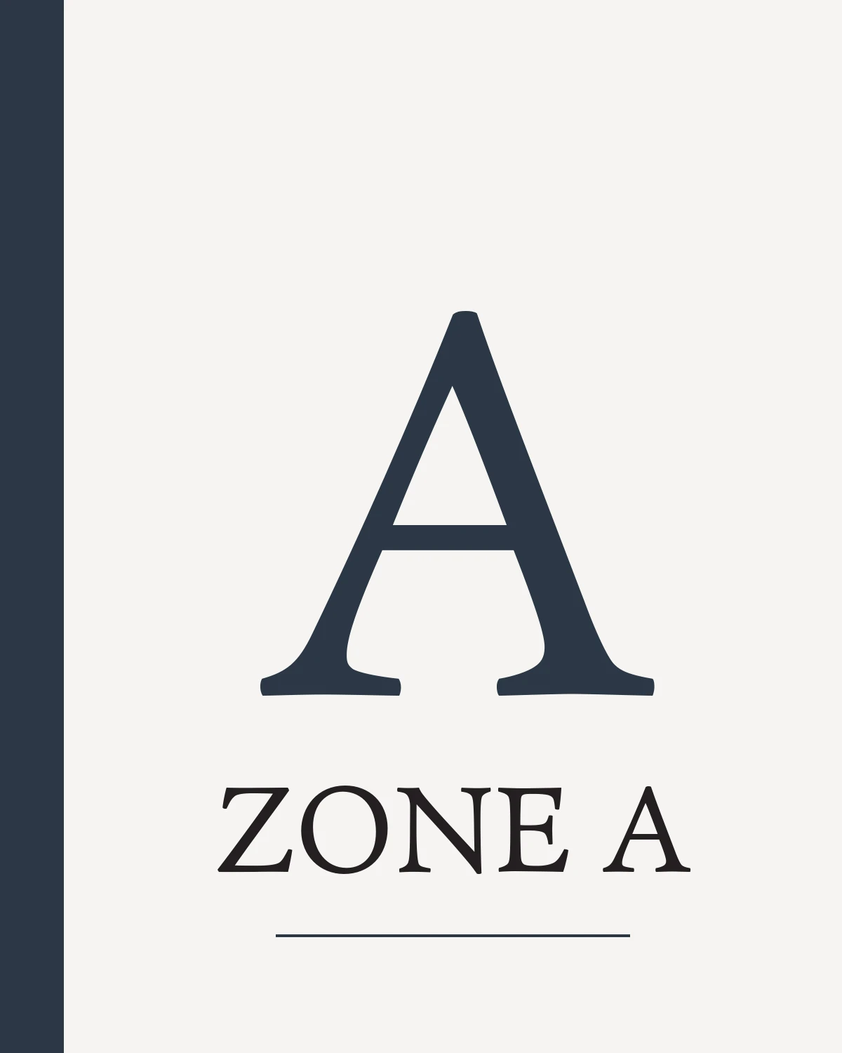
Approve A · Slate, B · Ashesi Red, C · Turquoise, D · Chocolate — white type on all four.
Approve navigation led by destinations, essential services and room ranges, with wing color as reinforcement.
Approve wall-mounted internal wayfinding as the design basis.
Approve the preferred visual treatment to take forward into detailed development.
What this proposal sets out
A five-level numbering system
Use neutral level numbers throughout the building.
This replaces public-facing terms such as Basement, Lower Ground, Ground Floor, First Floor and Mezzanine.
Because the site slopes, a visitor can enter the building at different architectural floors. Neutral numbering gives every entrance a clear and consistent reference.
The same level names will ultimately be used on
| Level | Replaces | Extent |
|---|---|---|
| 0Level 0 | Basement | Service accommodation |
| 1Level 1 | Lower Ground | Wings A, B, C and D |
| 2Level 2 | Ground Floor | Wings A, B, C and D |
| 3Level 3 | First Floor | Wings A, B, C and D |
| 4Level 4 | Mezzanine | Wing C only |
Four lettered wings
The eight architectural blocks are grouped into four lettered wings, A to D. Visitors are not expected to learn, or consciously navigate to, a wing.
Why keep the wing letters?
The original concept gave A–D a prominent navigational role because the building’s repeated geometry creates a need for stronger spatial orientation. Review showed that asking visitors to consciously navigate by wings added an unnecessary layer of abstraction.
The revised system keeps the useful part of that idea without making it a prerequisite for navigation. A–D now form part of the building’s addressing architecture: they make room references unique, they group room ranges, and they provide a secondary visual cue through color. Navigation itself remains led by destinations, essential services and room ranges.
This is not simply “dropping wings.” The letters do real work inside the address and quietly reinforce where you are — without becoming something a visitor has to decode before they can move.
One address, from anywhere on campus
Ashesi has multiple buildings, so a room number needs to work before someone enters the building. The STEM Center uses a campus-wide location reference that combines the building, wing, level and room.
Building + Wing + Level + Room
The same reference works on
Within the building, signs may use the shorter C201 where the building context is already obvious.
Wall-mounted internal wayfinding
All internal wayfinding is proposed as wall-mounted.
The proposal does not rely on suspended corridor signs, ceiling-mounted signs or freestanding interior pylons.
Whiteboards, projector areas, glazing, curtain walling, cabinetry and other unavailable surfaces need to be identified before final positions are approved.
One visual system, applied at different scales

 Pesaro, shown at display size
The system combines a restrained neutral base with the four wing colors. Large level numbers and wing letters do the orientation work. Detailed information remains quieter.
The goal is a system that feels part of Ashesi’s brand style.
Six conditions the wayfinding responds to
The building sets a handful of specific conditions. Each shapes the system — none means the architecture is deficient.
Repeated architecture
Several parts of the building — the four lettered wings — share a similar architectural character. A visitor can move from one part to another without a strong architectural signal that their location has changed.
Loop circulation
Levels 2 and 3 wrap around the central courtyard, so multiple plausible routes exist. If someone turns the wrong way, the route can still look correct because the corridor continues.
Multiple exterior arrival points
The building sits on a slope, so visitors may enter directly from outside onto different levels — someone entering from one side arrives on a different level from someone entering elsewhere.
Different vertical cores
Not every lift or stair serves exactly the same destinations. The Wing C library lift, for example, forms part of a specific route between the Quad, the Library and the Upper Library.
Overlapping uses
Teaching, research, the library, administration, senior leadership and technical spaces coexist within the building. A visitor can move from a public area toward a restricted one without a strong threshold.
A changing floor footprint
The building footprint changes between levels — the four-wing arrangement does not exist on every floor. This is an architectural condition rather than a visitor problem.
- Level 0 — service accommodation
- Level 1 — Wings A, B, C and D
- Level 2 — Wings A, B, C and D
- Level 3 — Wings A, B, C and D
- Level 4 — Wing C only
Orient → Direct → Confirm → Name
The signage follows one consistent sequence.
Orient
Where am I?At entrances, lift arrivals, stair arrivals and major thresholds. Establish Building · Level · the wing you are in before anyone is asked to find an individual room.
Direct
Which way do I go?Only where someone has to make a choice. Directional signs lead with destinations, the essential services and the room ranges that show which way an address lies — never an instruction to navigate to a wing. No sign carries more than five lines.
Confirm
Have I arrived?Every destination shows its room address and functional name together — C201, Biochemistry Lab, STEM C201.
Name
What is this place called?Donor, honorary and named-space recognition comes only after the functional identity is clear. A future name should never make a room harder to find.
How a visitor is guided
Every sign is built from the same order of priorities — destination first, wing color last.
Essential destinations remain visible
Some destinations should be findable without knowing a room number. They appear consistently at the decision points where a visitor genuinely needs them, rather than on every sign.
At lifts, stairs and important junctions, the room ranges lying in each direction let a visitor choose a way before they know exactly where a room is — for example, ← A301–A318 and C301–C320 →, with a major destination named where it helps.
Proposed sign system
The system is organized into five families.
Exterior & Site
Everything before the door or between campus destinations.- Building identification
- Entrance and level identification
- Campus directional signs
Wayfinding
Everything that helps someone move through the building.- Floor directory and directional
- Wing / room-range markers
- Core and level markers
- Washroom directional
- Landing signs
Identification
Confirms that someone has reached the right destination.- Room identification
- Department and open-plan identification
- Technical and service room identification
Regulatory & Safety
Statutory information, to the relevant safety standards.- Fire and escape information
- Laboratory hazard and PPE signage
- Restricted-access signage
- Accessibility information
Naming & Recognition
Added after the functional identity is working.- Named spaces
- Donor recognition
- Dedications
- Interpretive content
Design direction
The visual studies explore a system built around:
What should remain consistent across every visual option
The visual expression may change. The underlying wayfinding logic should not. Every option should retain:
Color and legibility
The four proposed wing colors have been checked for text contrast.
Slate
#2C3846
Ashesi Red
#A93C40
Turquoise
#017597
Turquoise works well for large wing letters and short labels. Longer or smaller text should generally sit on a neutral field.
Chocolate
#603913
The wing letter always remains visible. Color is reinforcement, not the only locator.
Readability is measured, not assumed
The proposed dimensions respond to how far away each sign is expected to be read.
| Sign | Typical reading distance | Working cap height |
|---|---|---|
| W02 Wing gateway sign | 8 m label | 165 mm letter · 34 mm label |
| E01 Building identification | 30 m | 150 mm |
| W03 Core and level marker | 6 m | 75 mm numeral · 16 mm tactile |
| W01 Floor directory and directional | 5 m rows · 2 m references | 54 mm level · 25 mm rows · 11 mm references |
| W06 Gateway floor directory | 5 m rows · 2 m plan | 54 mm level · 23 mm rows · 13 mm plan labels |
| E02 Entrance and level sign | 8 m | 40 mm level · 30 mm wing |
| W05 Landing sign | 5 m ranges | 40 mm ranges · 34 mm level · 26 mm rows |
| W04 Washroom directional | 5 m | 34 mm |
| I02 Department sign | 4 m | 30 mm number · 14 mm name |
| R04 Accessible route sign | 5 m | 25 mm heading · 20 mm destinations |
| E03 Campus directional | 5 m | 25 mm |
| I01 Standard room sign | 1.5–2 m | 24 mm number · 14 mm name |
| N01 Named space | 1.5–2 m | 24 mm number · 14 mm name |
| I03 Technical and service room | 1.5 m | 20 mm number · 14 mm name |
Text is also measured against the actual typeface before plate dimensions are fixed.
Check a cap height against a distance
Minimum cap height is the viewing distance divided by 250; the preferred figure divides by 200. Move either slider to test a sign against the distance it will actually be read from.
- Minimum
- —
- Preferred
- —
Current working widths
Accessibility
Accessible wayfinding should not be treated as a variation of the standard route.
Where a ramp or lift route differs from the most direct stair route, the signage system should identify both.
Naming should be designed to change
Room functions and donor names will change over the life of the building.
Where a sign may later carry a name, it should be designed as two parts if possible:
Permanent carrier
- Room reference
- Wing information
- Permanent system elements
Replaceable insert
- Room or space name
- Future donor or honorary naming
This allows a naming decision to change an insert rather than require a new sign and new wall fixings.
If this is not possible, we should maintain the existing screw-on plates that can be swapped without needing new wall drilling.
Sign mockups
The same five signs, drawn for each of the four wings. Dimensions and cap heights are the proposed working modules; type is Pesaro for lead information and Poppins for supporting.
#2C3846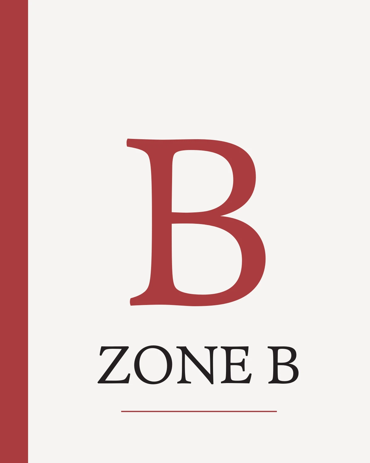
#A93C40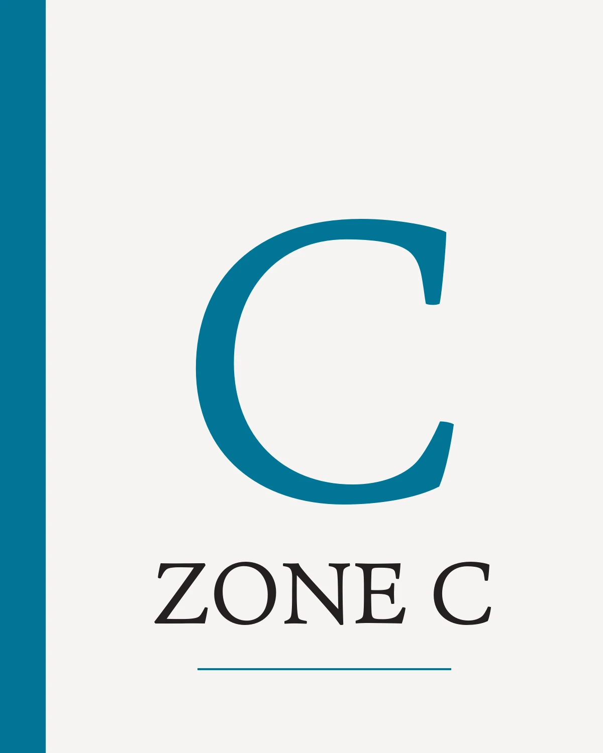
#017597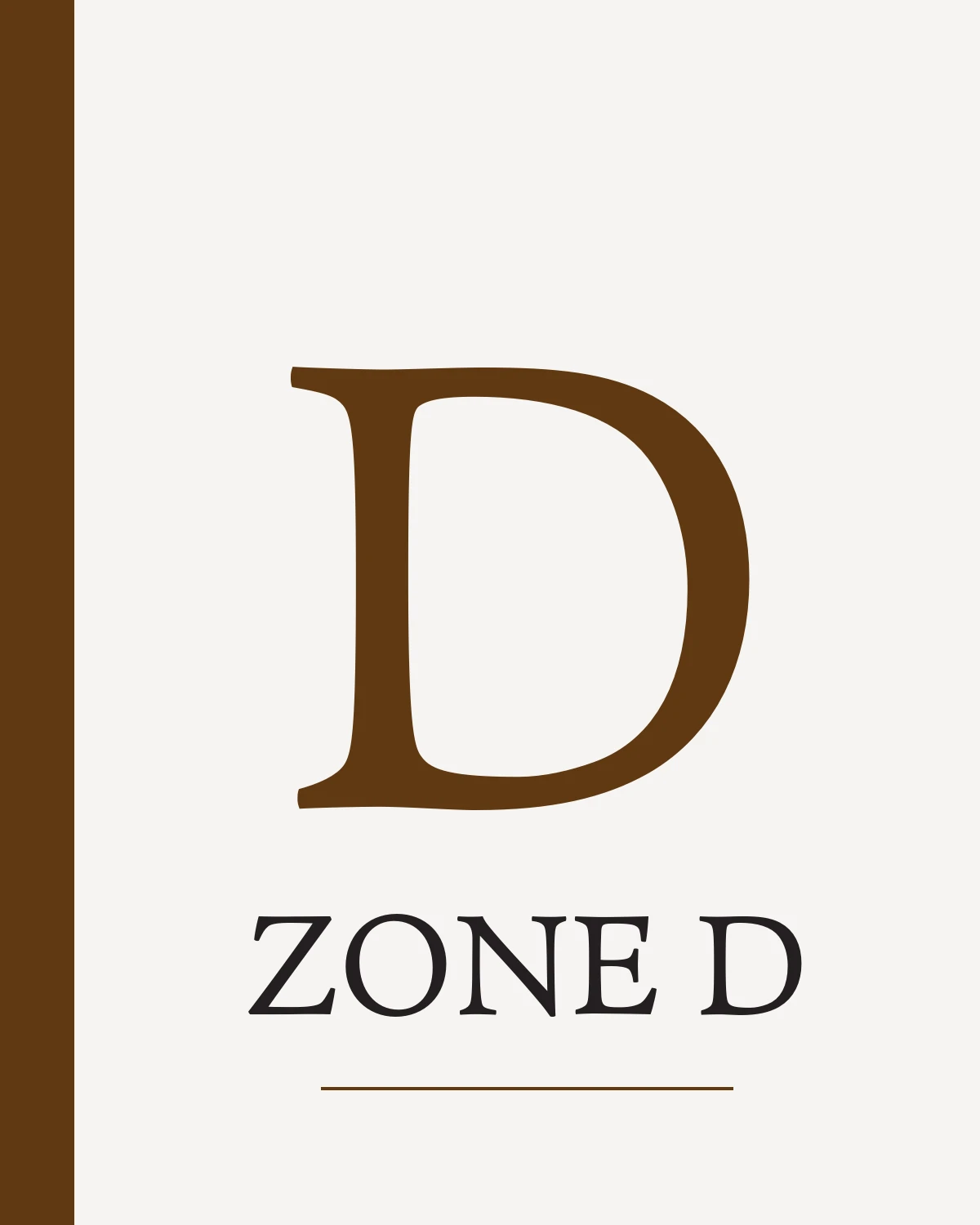
#603913What changes between wings, and what does not
Fixed
- Sign dimensions and cap heights
- Layout and information order
- White ACM panel with a painted wing edge
- Pesaro for lead information, Poppins for supporting
- The wing named in words on every cue
Varies
- The wing color and letter
- The levels each wing actually reaches
- Destinations and room references
The types in a wing set
| Type | Sign | Size | Cap height | Read from |
|---|---|---|---|---|
| E02 | Entrance and level sign | 600 × 400 mm | 40 mm level · 30 mm wing | 8 m |
| W02 | Wing gateway sign | 450 × 450 mm | 165 mm letter · 34 mm label | 8 m label |
| W01 | Floor directory and directional | 1200 × 1198 mm | 54 mm level · 25 mm rows · 11 mm references | 5 m rows · 2 m references |
| W03 | Core and level marker | 300 × 300 mm | 75 mm numeral · 16 mm tactile | 6 m |
| W04 | Washroom directional | 560 × 250 mm | 34 mm | 5 m |
| W05 | Landing sign | 800 × 520 mm | 40 mm ranges · 34 mm level · 26 mm rows | 5 m ranges |
| W06 | Gateway floor directory | 1200 × 1398 mm | 54 mm level · 23 mm rows · 13 mm plan labels | 5 m rows · 2 m plan |
| R04 | Accessible route sign | 700 × 520 mm | 25 mm heading · 20 mm destinations | 5 m |
| I01 | Standard room sign | 360 × 240 mm | 24 mm number · 14 mm name | 1.5–2 m |
| I02 | Department sign | 480 × 300 mm | 30 mm number · 14 mm name | 4 m |
| I03 | Technical and service room | 360 × 180 mm | 20 mm number · 14 mm name | 1.5 m |
| N01 | Named space | 360 × 240 mm | 24 mm number · 14 mm name | 1.5–2 m |
Not wing-specific
Two exterior types identify the building rather than a wing, so they are shown once rather than four times.

- Size
- 2000 × 480 mm
- Cap height
- 150 mm
- Read from
- 30 m
Individually pinned letters read from the access road. The plate is sized to the specified cap height rather than the cap height shrunk to fit a plate — at 150 mm the name needs 1,592 mm of face.
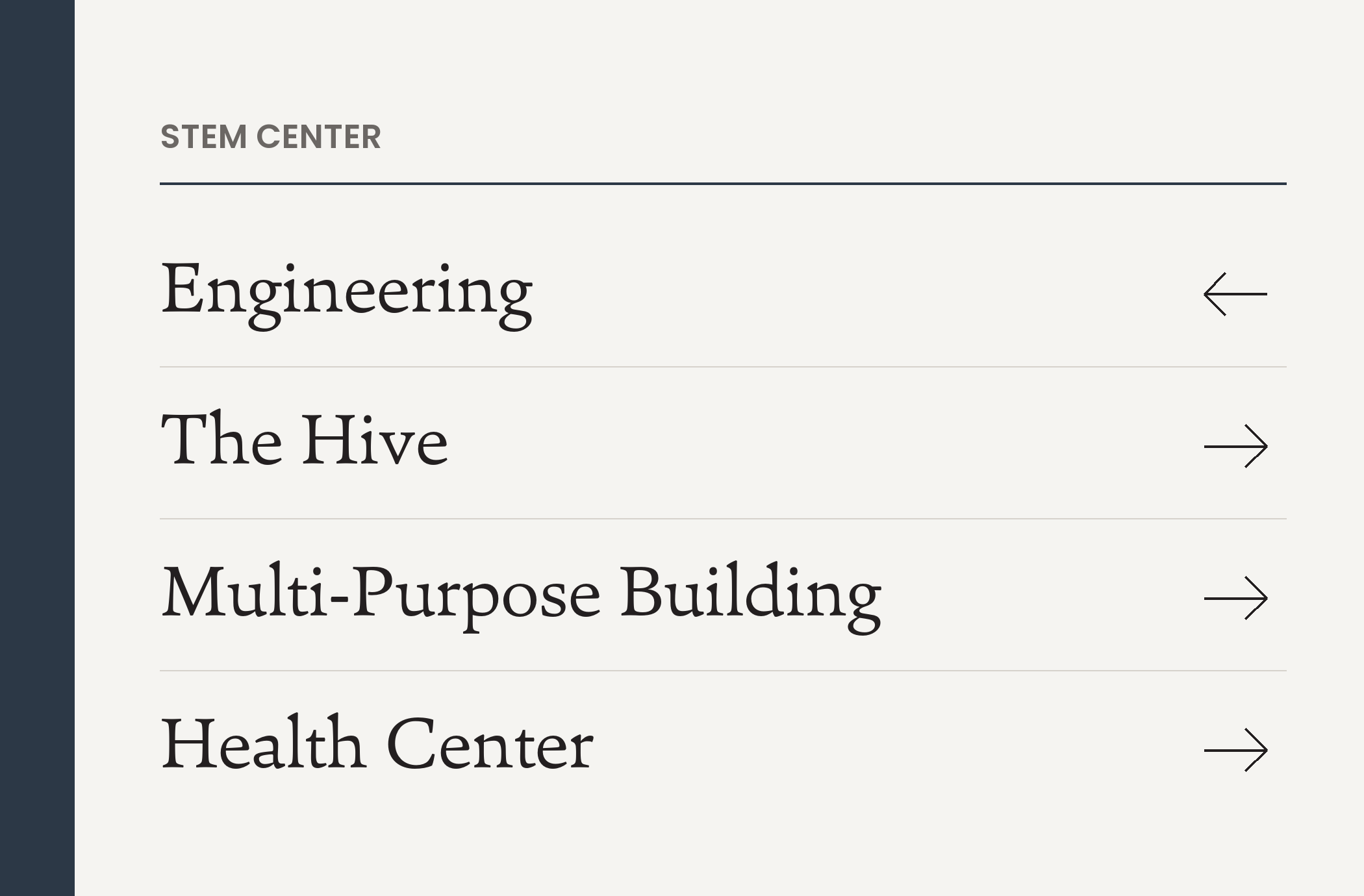
- Size
- 700 × 520 mm
- Cap height
- 25 mm
- Read from
- 5 m
Opens with “You are here: STEM Center”, then hands the visitor off to the wider campus at each link: King Engineering Building, The Hive, the Multipurpose Building, the Fabrication Lab and Natembea Health Center. Carries campus destinations, never rooms inside this building — those belong on W01. The plate is sized to the five destinations rather than the list trimmed to fit.
Statutory signage
Fire and escape, laboratory hazard and PPE, and restricted access signage (R01–R03) are not drawn here. They follow the relevant safety standards, and Ashesi’s brand colors do not replace statutory safety colors or symbols. Donor recognition, dedications and interpretive content (N02–N04) wait on the naming program.
Wing A — the full set
Slate is the darkest of the four and the strongest against the panel at 10.84:1. Wing A has no lift of its own — only Wings B, C and D and the Quad carry one — so its directional signs route to the nearest core.
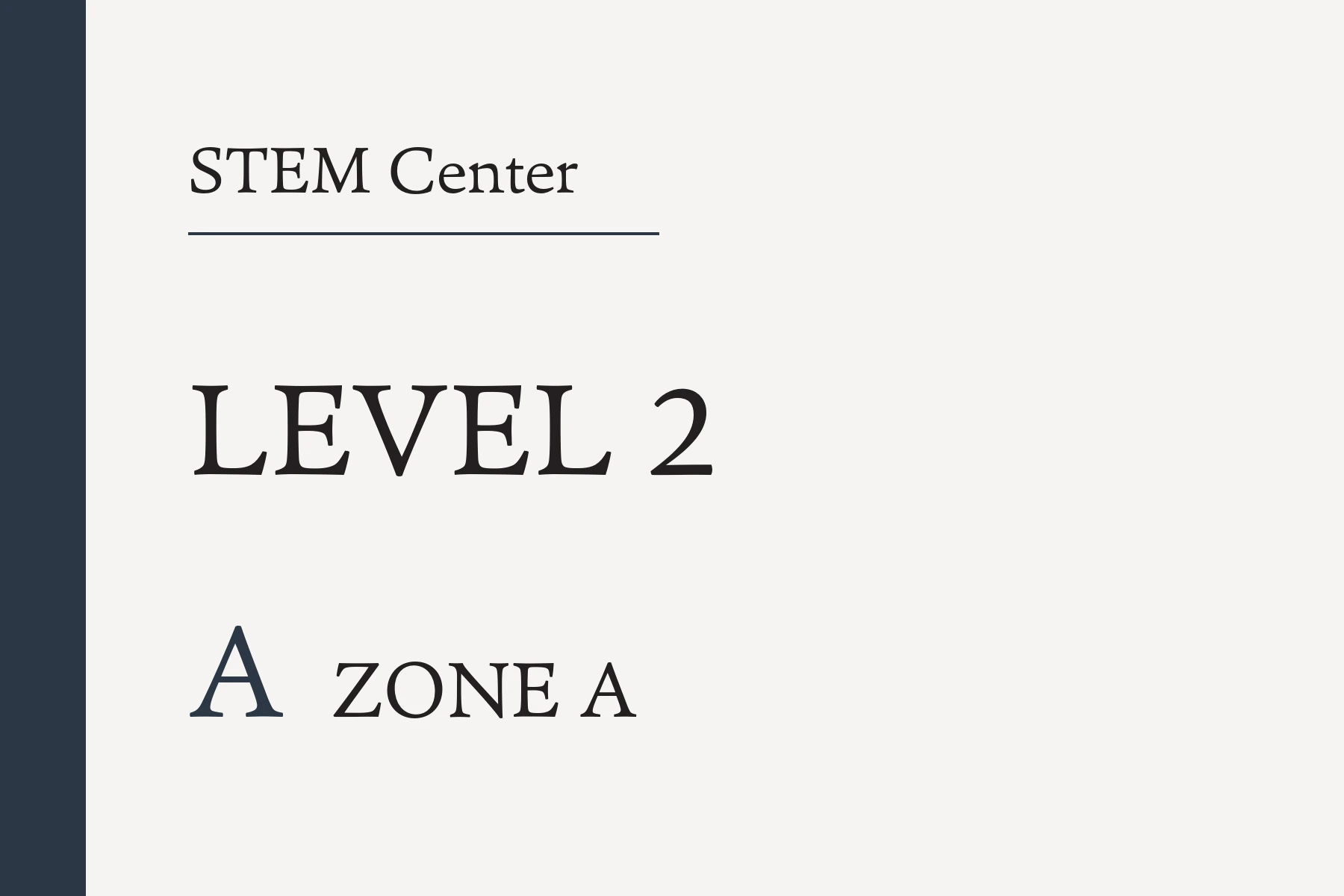
- Size
- 600 × 400 mm
- Cap height
- 40 mm level · 30 mm wing
- Read from
- 8 m
Names the building, the level being entered and the wing you are standing in. Because the site slopes, a visitor can enter directly from outside onto different levels, so every entrance carries one.
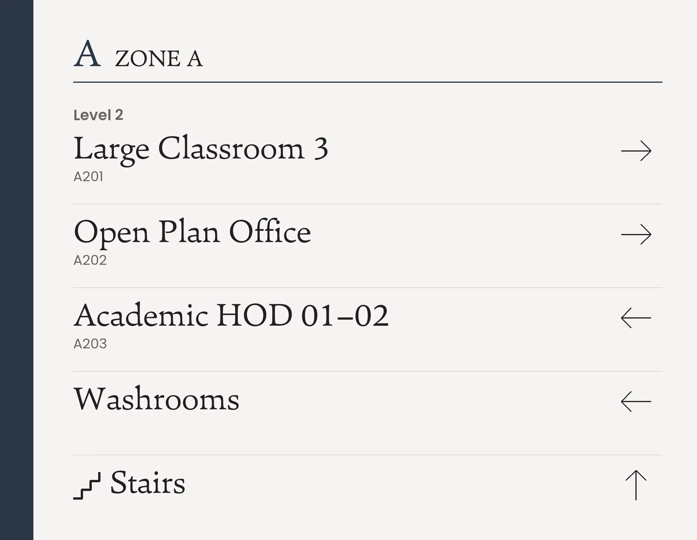
- Size
- 450 × 450 mm
- Cap height
- 165 mm letter · 34 mm label
- Read from
- 8 m label
The one sign that keeps the oversized letter above the label — it is read across a foyer and is what tells someone they have moved between four wings that otherwise look alike. Elsewhere the letter beside the same words only repeats itself, so those signs carry the label alone.
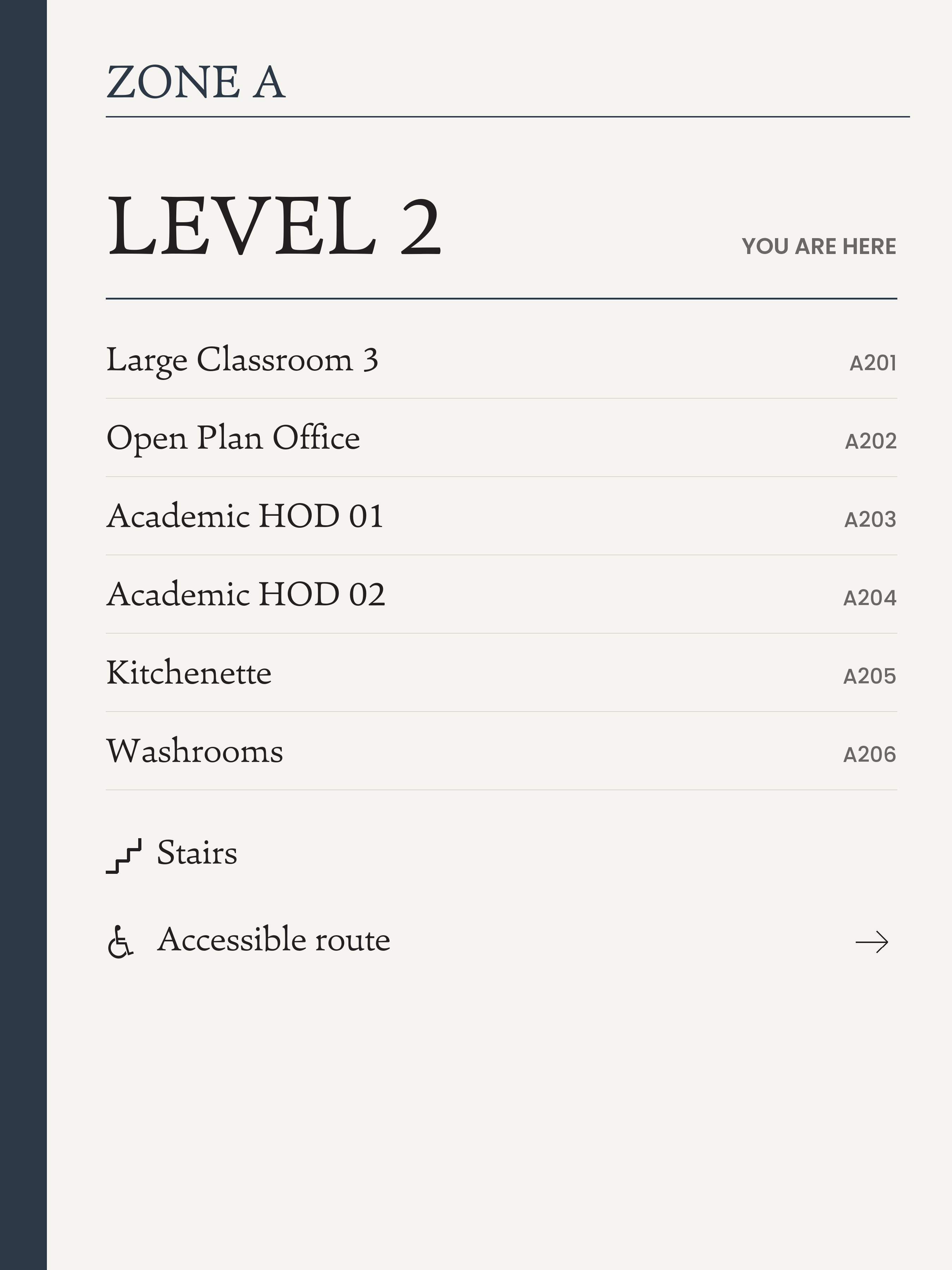
- Size
- 1200 × 1198 mm
- Cap height
- 54 mm level · 25 mm rows · 11 mm references
- Read from
- 5 m rows · 2 m references
One sign doing both jobs. Every row of the level listing carries its own arrow, so the same plate serves a foyer, a lift lobby, a stair head and a corridor decision point — the earlier scheme split this into a directory that listed and a directional that pointed. The core and the accessible route each keep their own line. The plate is sized to the wing’s list rather than trimmed to a fixed height, so Wing D runs 934 mm against 1,198 mm elsewhere.
- Size
- 300 × 300 mm
- Cap height
- 75 mm numeral · 16 mm tactile
- Read from
- 6 m
Drawn at the scheduled 300 mm, so it carries the level and the core and nothing else — the visual numeral above a tactile line repeating it. Which levels a core actually reaches is directory content and belongs on W01, the sign a reader consults before choosing a core; Wing A has no lift at all, so its marker reads Stairs.
- Size
- 560 × 250 mm
- Cap height
- 34 mm
- Read from
- 5 m
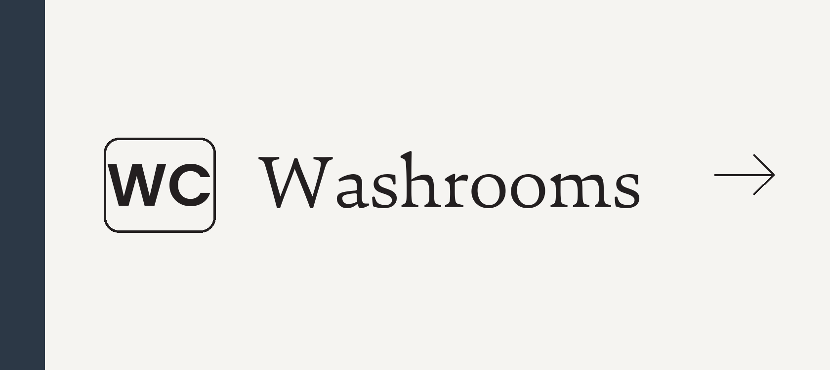
Entirely new. There were 29 washroom door signs in the schedule and nothing that directed anyone to one — washrooms sat as a text row on the floor directory. Ten of these go at corridor decision points, where a reader is furthest from a landing. The WC badge stands in for the supplied ISO 7001 pictogram.
- Size
- 800 × 520 mm
- Cap height
- 40 mm ranges · 34 mm level · 26 mm rows
- Read from
- 5 m ranges
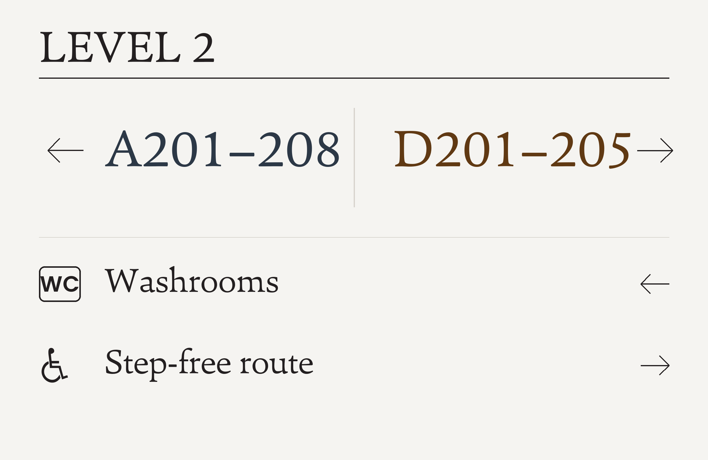
The hotel pattern, at all 24 lift and stair landings. The tactile core marker states the level and stops; this names where each direction leads. It works without renumbering because each wing and level is already a contiguous range.
- Size
- 1200 × 1398 mm
- Cap height
- 54 mm level · 23 mm rows · 13 mm plan labels
- Read from
- 5 m rows · 2 m plan
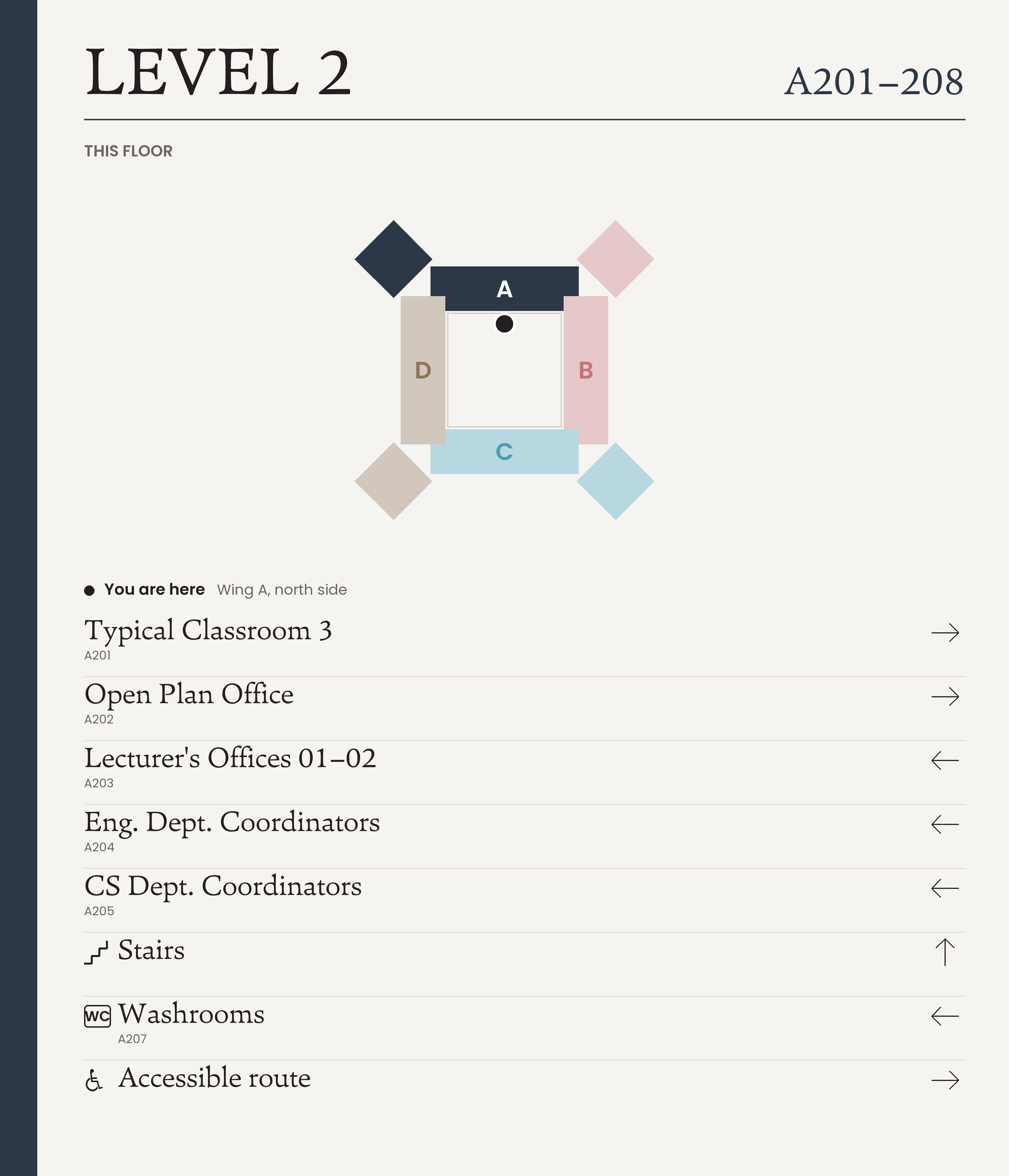
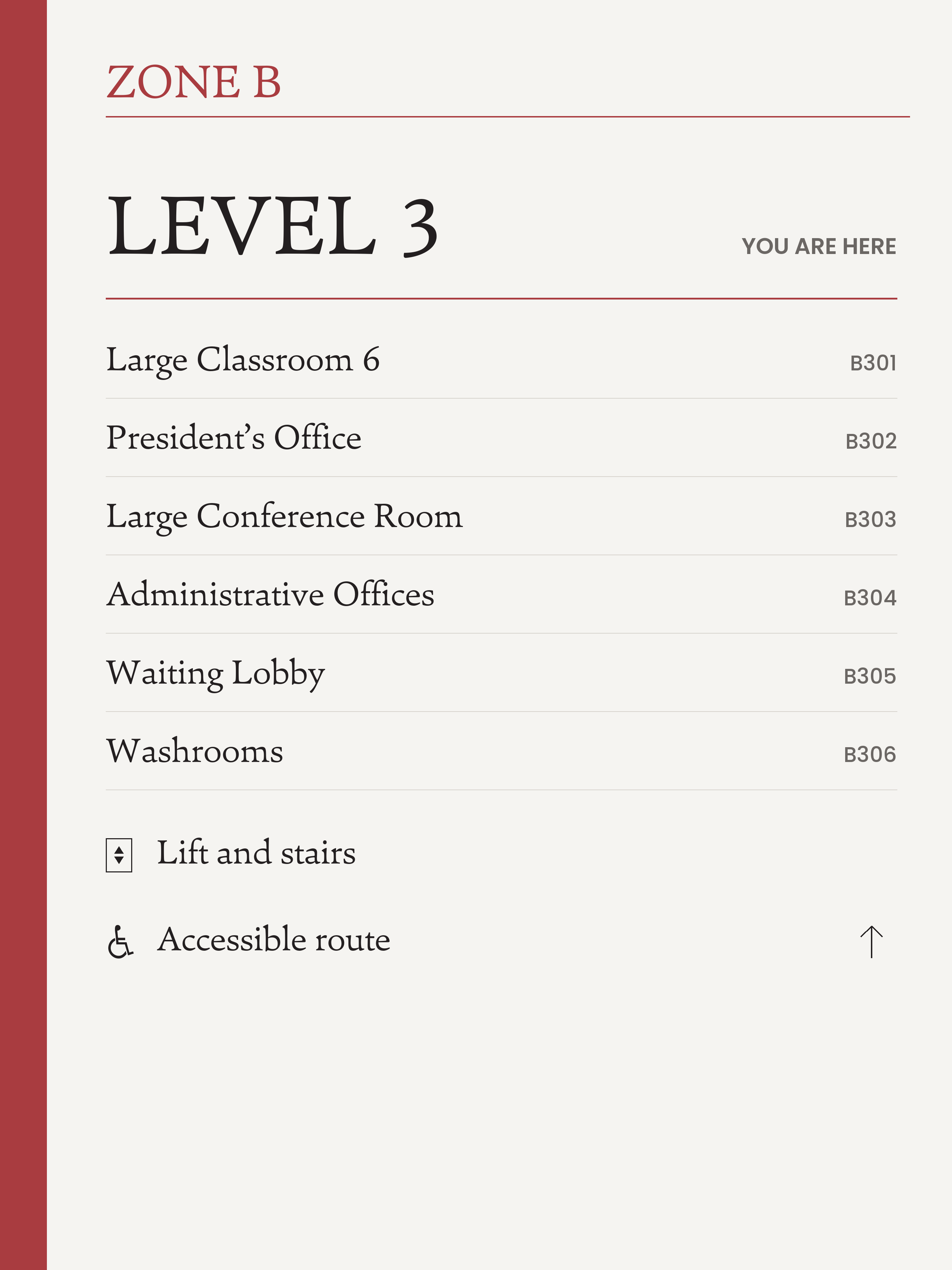
The gateway sign, reworked. Feedback in review was that announcing a wing can confuse rather than orient, so the wing marker becomes optional and this takes the gateway role — a simplified plan of the whole floor with a you-are-here mark, over the destinations on this level. The list is capped at five destinations: the plan does the orienting, and a taller plate would push the top line past the 1600 mm the spec allows for anything that has to be read. None are placed on the plans yet — the schedule will count them as they are added.
- Size
- 700 × 520 mm
- Cap height
- 25 mm heading · 20 mm destinations
- Read from
- 5 m
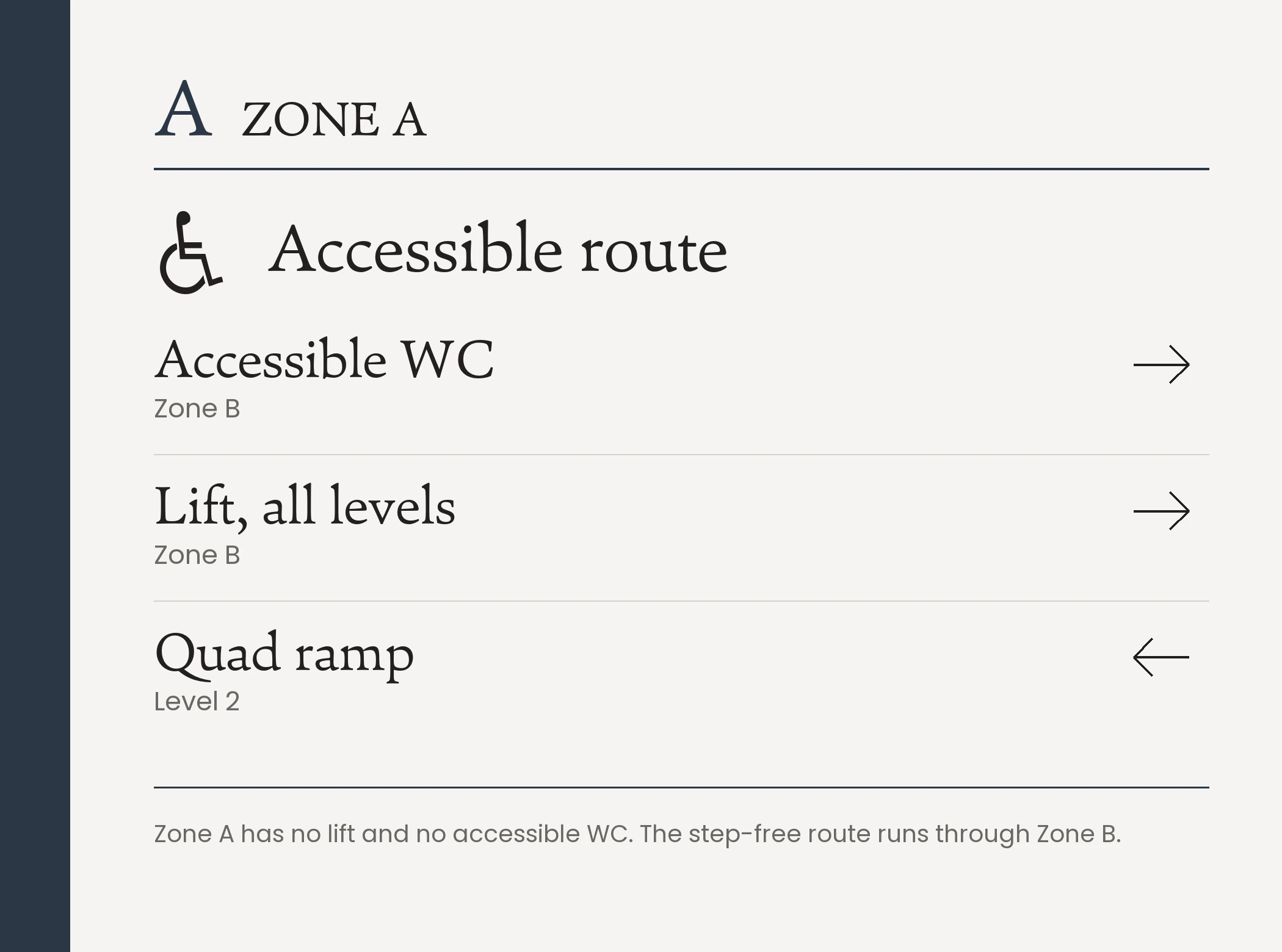
The accessible route is stored and signed separately from the direct one. Where a wing cannot provide step-free access itself, the sign says so and routes out of the wing rather than leaving someone to discover it.
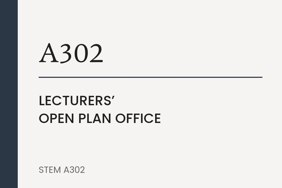
- Size
- 360 × 240 mm
- Cap height
- 24 mm number · 14 mm name
- Read from
- 1.5–2 m
The number leads, because it is the permanent estate identifier; the name sits beneath it on the replaceable insert. Renaming a room costs an insert rather than a sign and new wall fixings.

- Size
- 480 × 300 mm
- Cap height
- 30 mm number · 14 mm name
- Read from
- 4 m
The same plate family at a larger module, for departments and open-plan areas that have no single door and are read from further away.
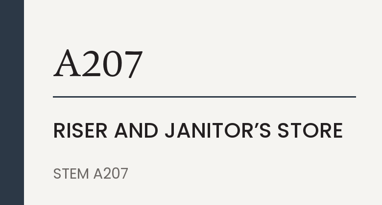
- Size
- 360 × 180 mm
- Cap height
- 20 mm number · 14 mm name
- Read from
- 1.5 m
The smallest plate in the set, for risers, stores and plant. Read at the door and nowhere else, so it carries the reference and nothing more.
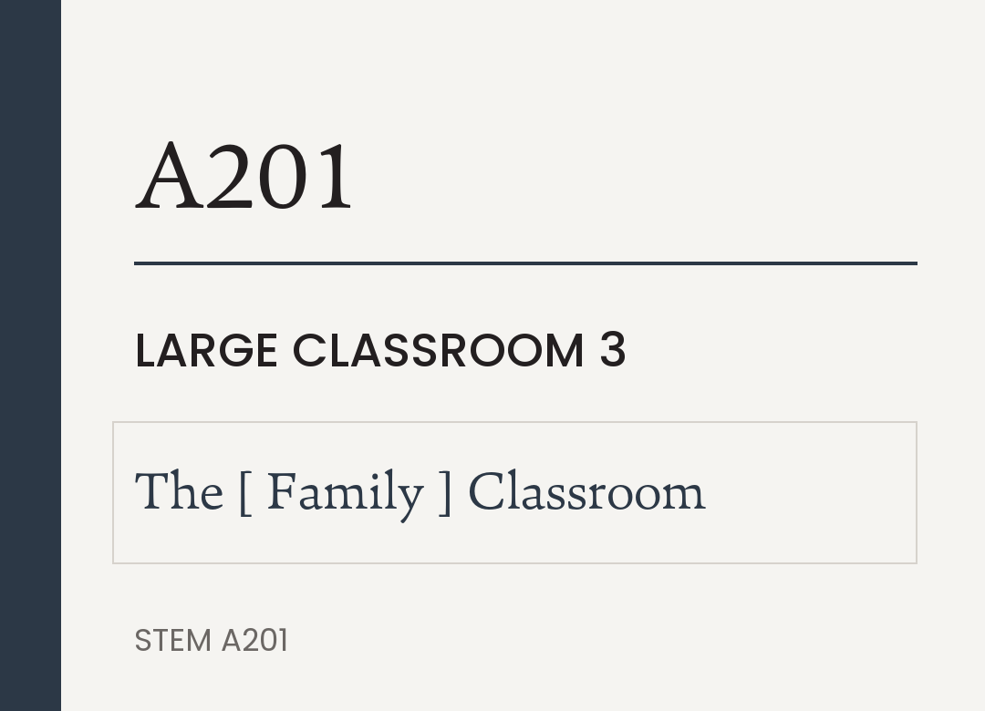
- Size
- 360 × 240 mm
- Cap height
- 24 mm number · 14 mm name
- Read from
- 1.5–2 m
The room sign’s carrier with the naming insert in place of the room’s name: the number, then the named space on two lines — The Ashesi Foundation Classroom. The room’s own name is not repeated. The name shown is a placeholder for the mechanism, not a proposal — naming has not been decided, and nothing in the package waits on it.
Wing B — the full set
Ashesi Red is the brand color doing double duty as a wing cue. It reads clearly at 5.6:1, but it is worth confirming that a red edge is understood as “Wing B” rather than simply as Ashesi branding.
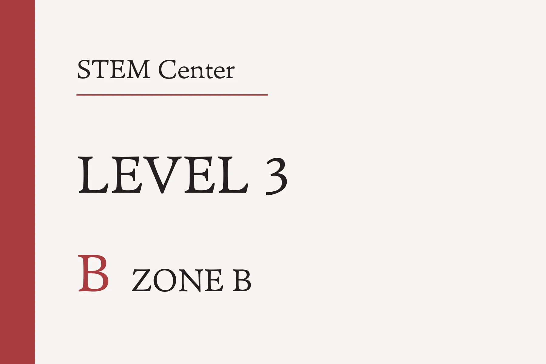
- Size
- 600 × 400 mm
- Cap height
- 40 mm level · 30 mm wing
- Read from
- 8 m
Names the building, the level being entered and the wing you are standing in. Because the site slopes, a visitor can enter directly from outside onto different levels, so every entrance carries one.
- Size
- 450 × 450 mm
- Cap height
- 165 mm letter · 34 mm label
- Read from
- 8 m label
The one sign that keeps the oversized letter above the label — it is read across a foyer and is what tells someone they have moved between four wings that otherwise look alike. Elsewhere the letter beside the same words only repeats itself, so those signs carry the label alone.
- Size
- 1200 × 1198 mm
- Cap height
- 54 mm level · 25 mm rows · 11 mm references
- Read from
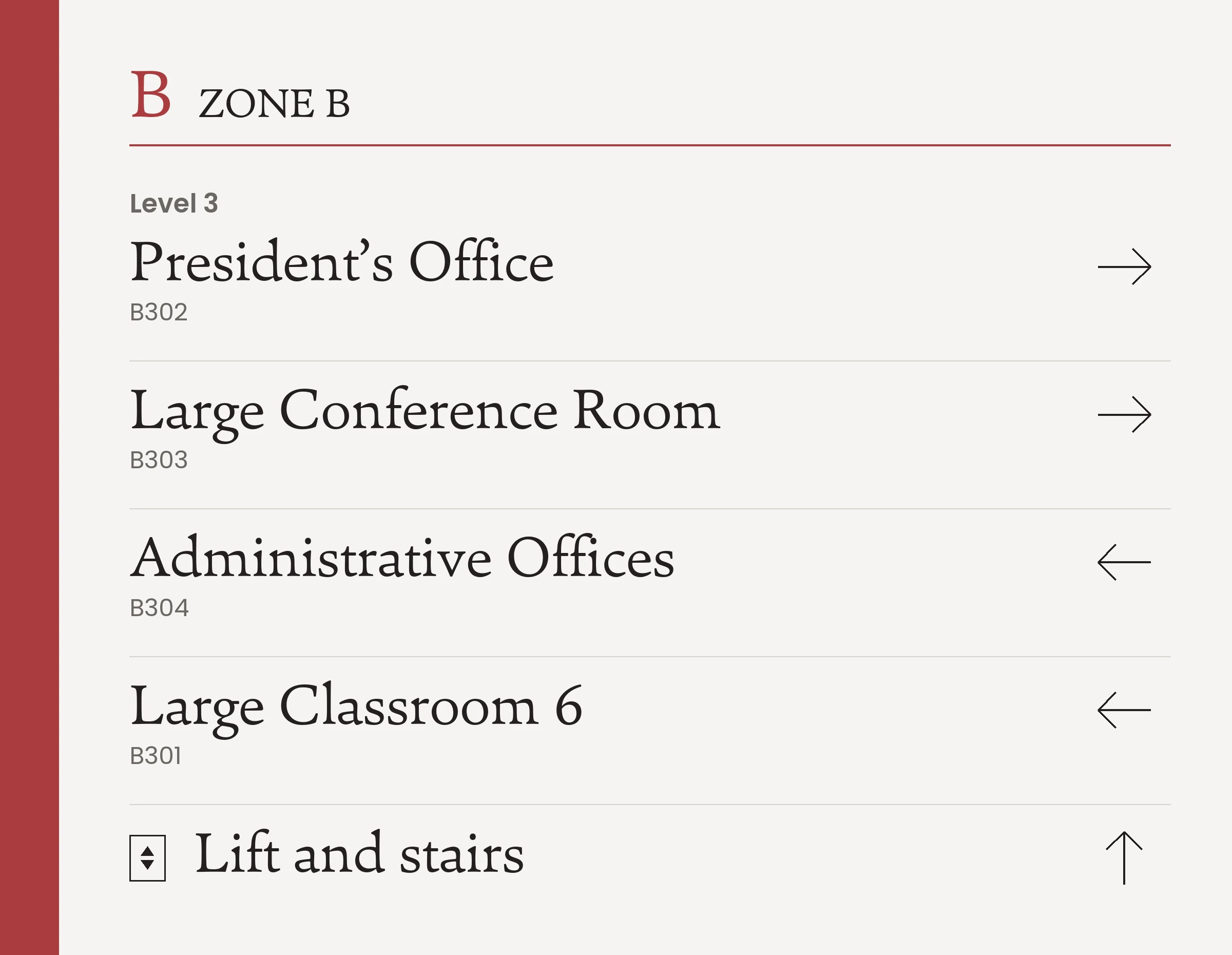
- 5 m rows · 2 m references
One sign doing both jobs. Every row of the level listing carries its own arrow, so the same plate serves a foyer, a lift lobby, a stair head and a corridor decision point — the earlier scheme split this into a directory that listed and a directional that pointed. The core and the accessible route each keep their own line. The plate is sized to the wing’s list rather than trimmed to a fixed height, so Wing D runs 934 mm against 1,198 mm elsewhere.
- Size
- 300 × 300 mm
- Cap height
- 75 mm numeral · 16 mm tactile
- Read from
- 6 m
Drawn at the scheduled 300 mm, so it carries the level and the core and nothing else — the visual numeral above a tactile line repeating it. Which levels a core actually reaches is directory content and belongs on W01, the sign a reader consults before choosing a core; Wing A has no lift at all, so its marker reads Stairs.
- Size
- 560 × 250 mm
- Cap height
- 34 mm
- Read from
- 5 m
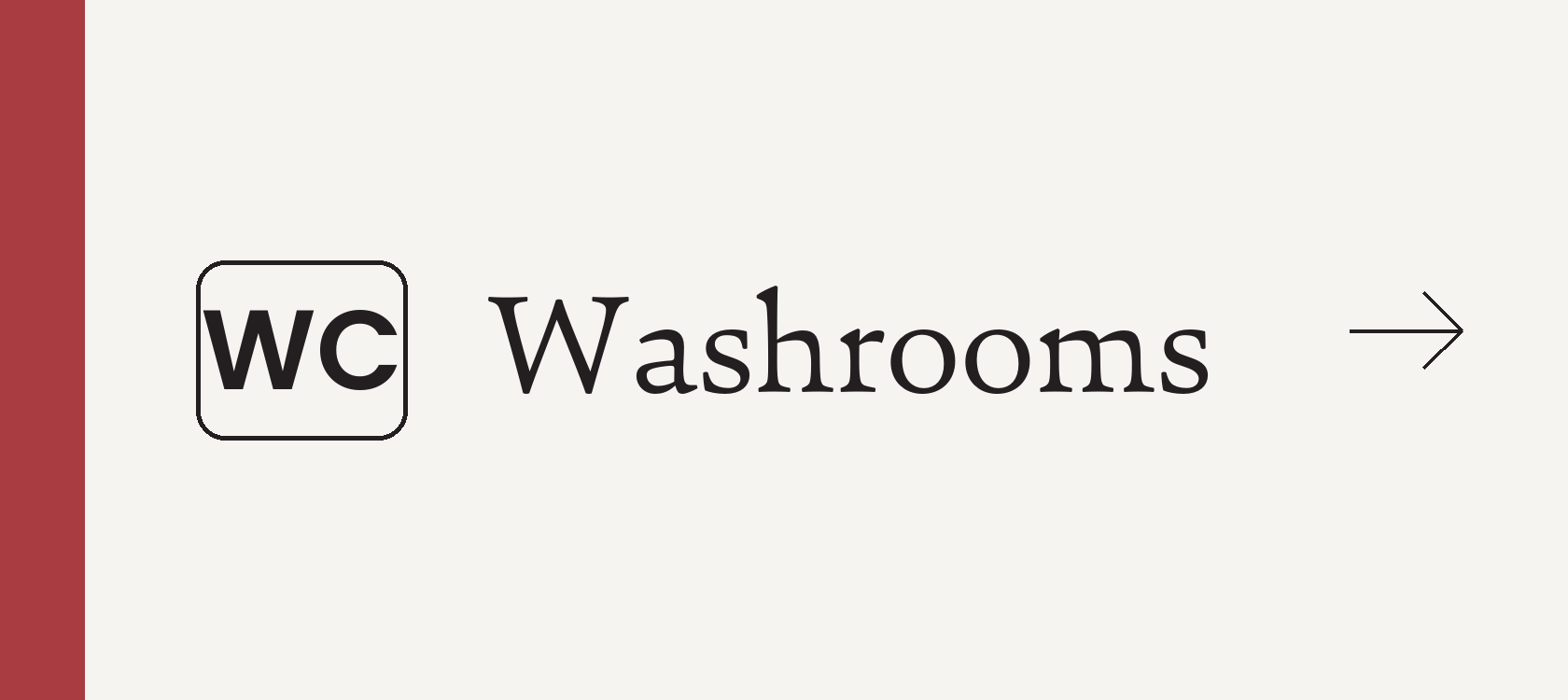
Entirely new. There were 29 washroom door signs in the schedule and nothing that directed anyone to one — washrooms sat as a text row on the floor directory. Ten of these go at corridor decision points, where a reader is furthest from a landing. The WC badge stands in for the supplied ISO 7001 pictogram.
- Size
- 800 × 520 mm
- Cap height
- 40 mm ranges · 34 mm level · 26 mm rows
- Read from
- 5 m ranges
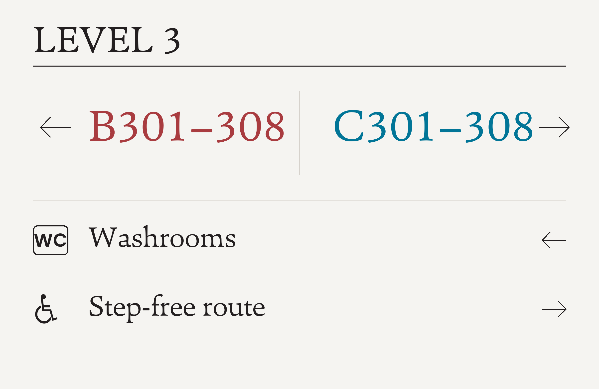
The hotel pattern, at all 24 lift and stair landings. The tactile core marker states the level and stops; this names where each direction leads. It works without renumbering because each wing and level is already a contiguous range.
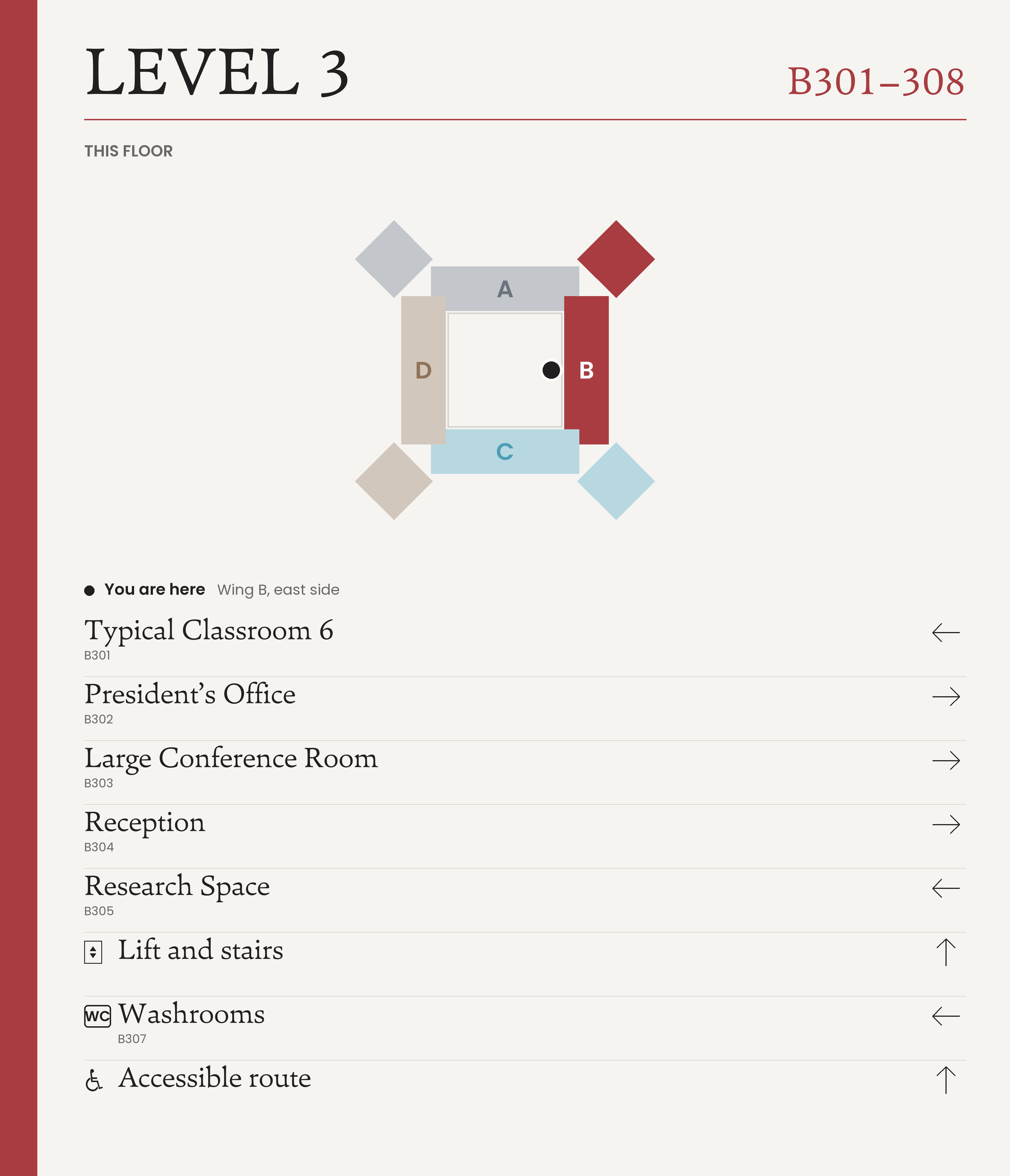
- Size
- 1200 × 1398 mm
- Cap height
- 54 mm level · 23 mm rows · 13 mm plan labels
- Read from
- 5 m rows · 2 m plan
The gateway sign, reworked. Feedback in review was that announcing a wing can confuse rather than orient, so the wing marker becomes optional and this takes the gateway role — a simplified plan of the whole floor with a you-are-here mark, over the destinations on this level. The list is capped at five destinations: the plan does the orienting, and a taller plate would push the top line past the 1600 mm the spec allows for anything that has to be read. None are placed on the plans yet — the schedule will count them as they are added.
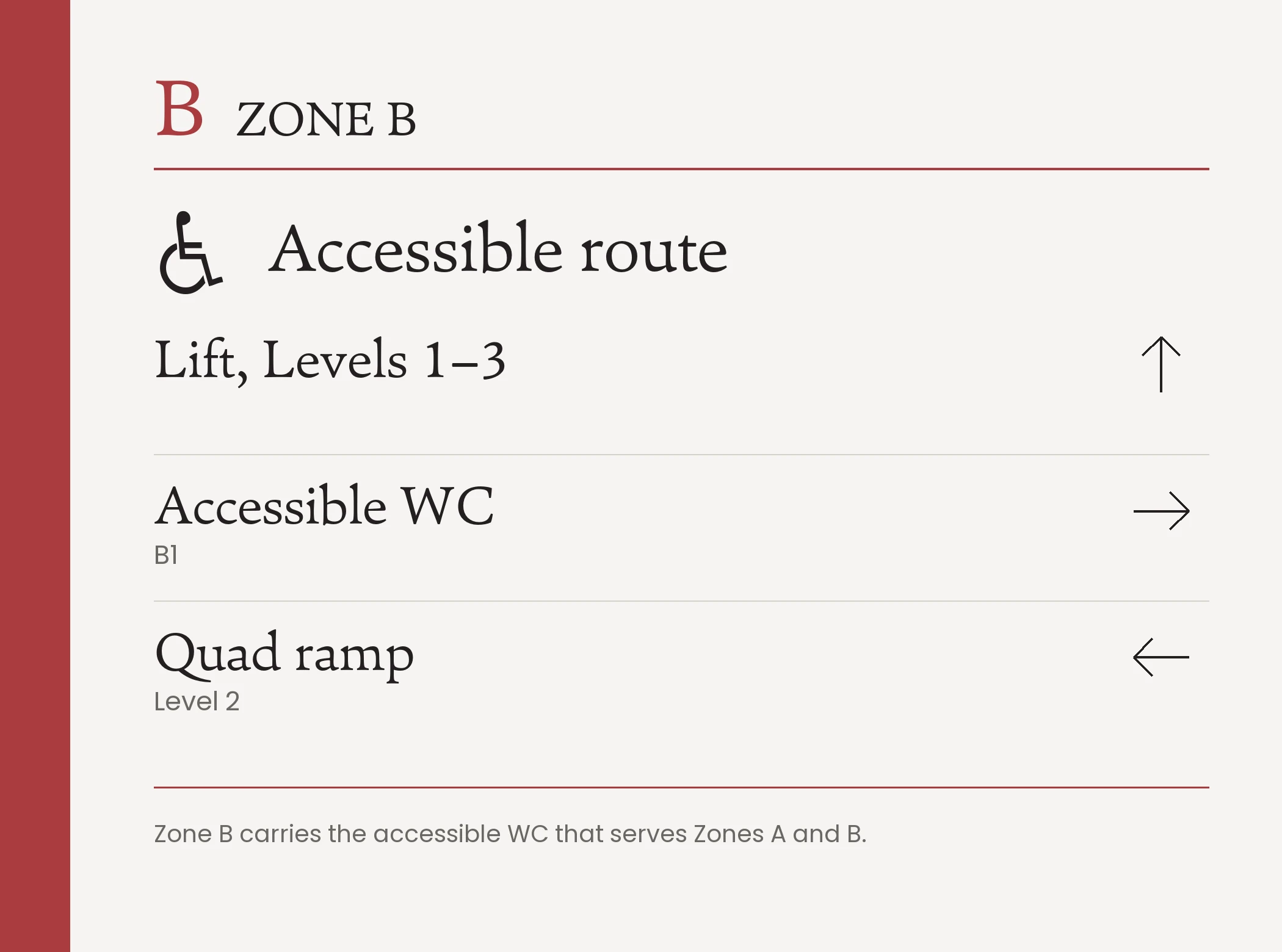
- Size
- 700 × 520 mm
- Cap height
- 25 mm heading · 20 mm destinations
- Read from
- 5 m
The accessible route is stored and signed separately from the direct one. Where a wing cannot provide step-free access itself, the sign says so and routes out of the wing rather than leaving someone to discover it.
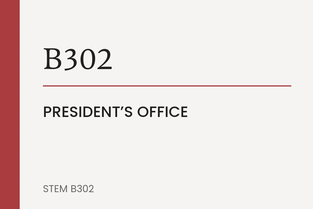
- Size
- 360 × 240 mm
- Cap height
- 24 mm number · 14 mm name
- Read from
- 1.5–2 m
The number leads, because it is the permanent estate identifier; the name sits beneath it on the replaceable insert. Renaming a room costs an insert rather than a sign and new wall fixings.
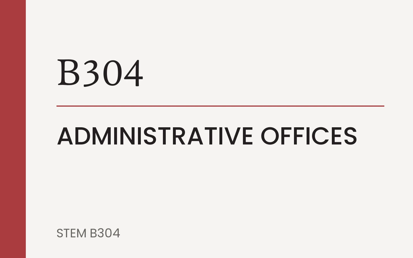
- Size
- 480 × 300 mm
- Cap height
- 30 mm number · 14 mm name
- Read from
- 4 m
The same plate family at a larger module, for departments and open-plan areas that have no single door and are read from further away.
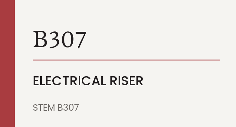
- Size
- 360 × 180 mm
- Cap height
- 20 mm number · 14 mm name
- Read from
- 1.5 m
The smallest plate in the set, for risers, stores and plant. Read at the door and nowhere else, so it carries the reference and nothing more.
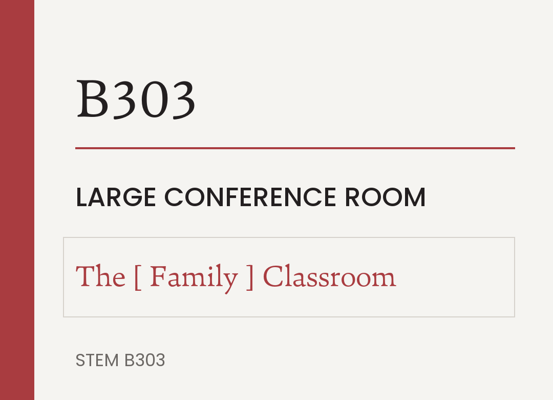
- Size
- 360 × 240 mm
- Cap height
- 24 mm number · 14 mm name
- Read from
- 1.5–2 m
The room sign’s carrier with the naming insert in place of the room’s name: the number, then the named space on two lines — The Ashesi Foundation Classroom. The room’s own name is not repeated. The name shown is a placeholder for the mechanism, not a proposal — naming has not been decided, and nothing in the package waits on it.
Wing C — the full set
Turquoise is the lightest of the four at 4.78:1 — comfortably above the minimum, but the narrowest margin in the set, which is why it carries short labels and large letters rather than dense copy.
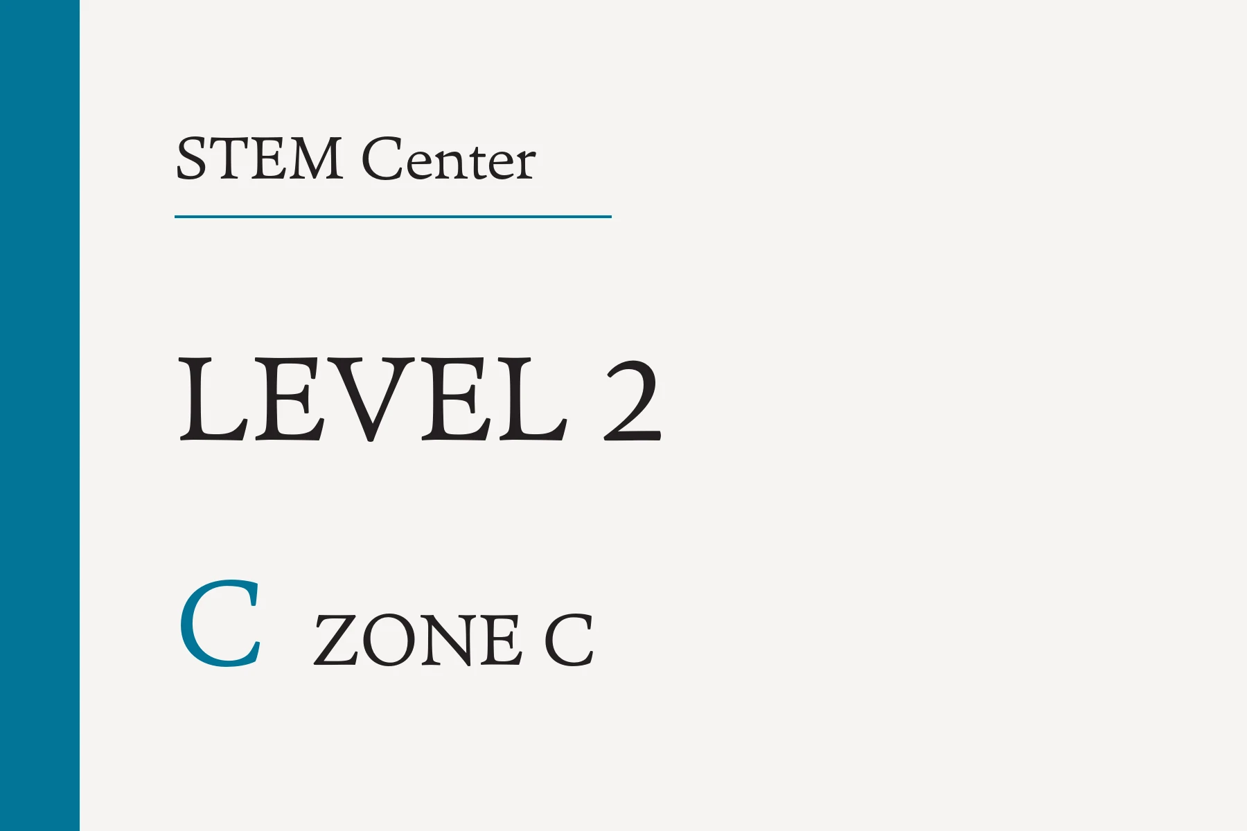
- Size
- 600 × 400 mm
- Cap height
- 40 mm level · 30 mm wing
- Read from
- 8 m
Names the building, the level being entered and the wing you are standing in. Because the site slopes, a visitor can enter directly from outside onto different levels, so every entrance carries one.
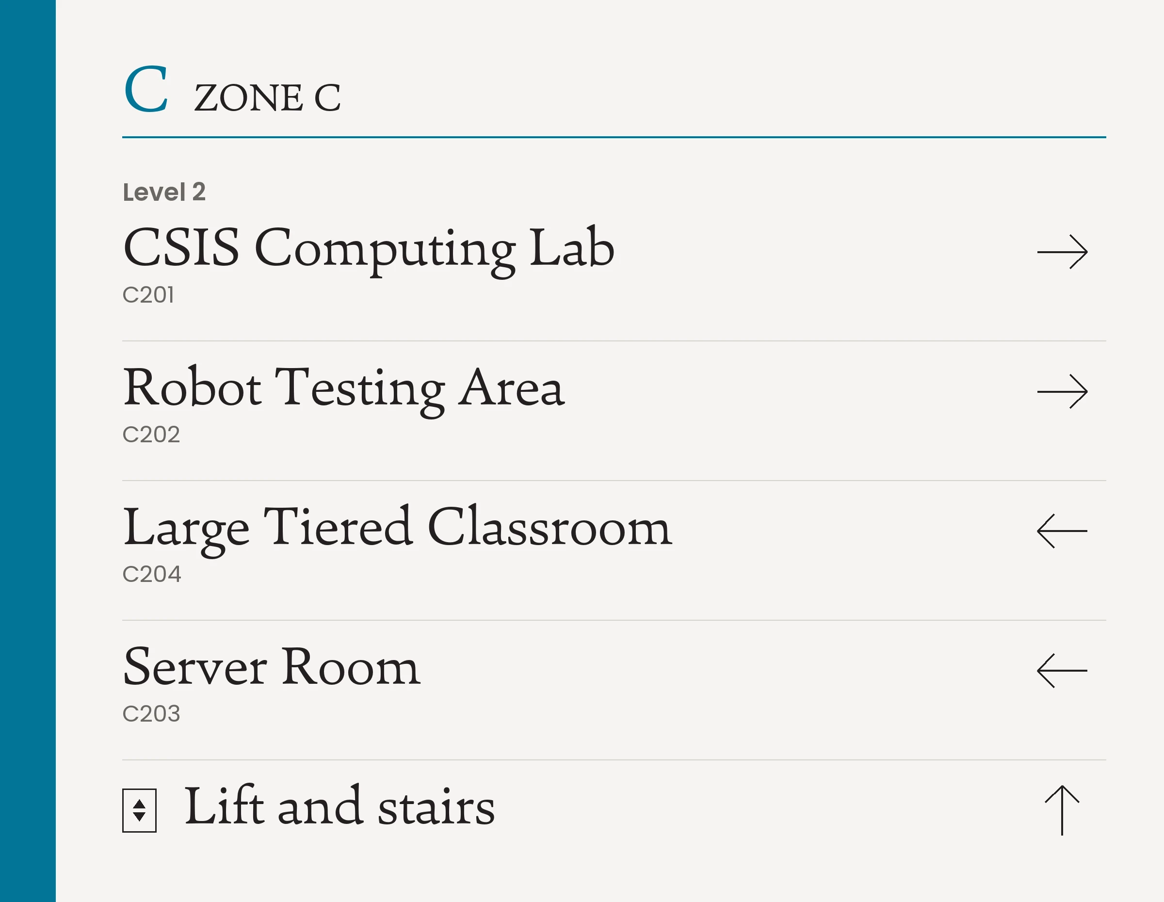
- Size
- 450 × 450 mm
- Cap height
- 165 mm letter · 34 mm label
- Read from
- 8 m label
The one sign that keeps the oversized letter above the label — it is read across a foyer and is what tells someone they have moved between four wings that otherwise look alike. Elsewhere the letter beside the same words only repeats itself, so those signs carry the label alone.
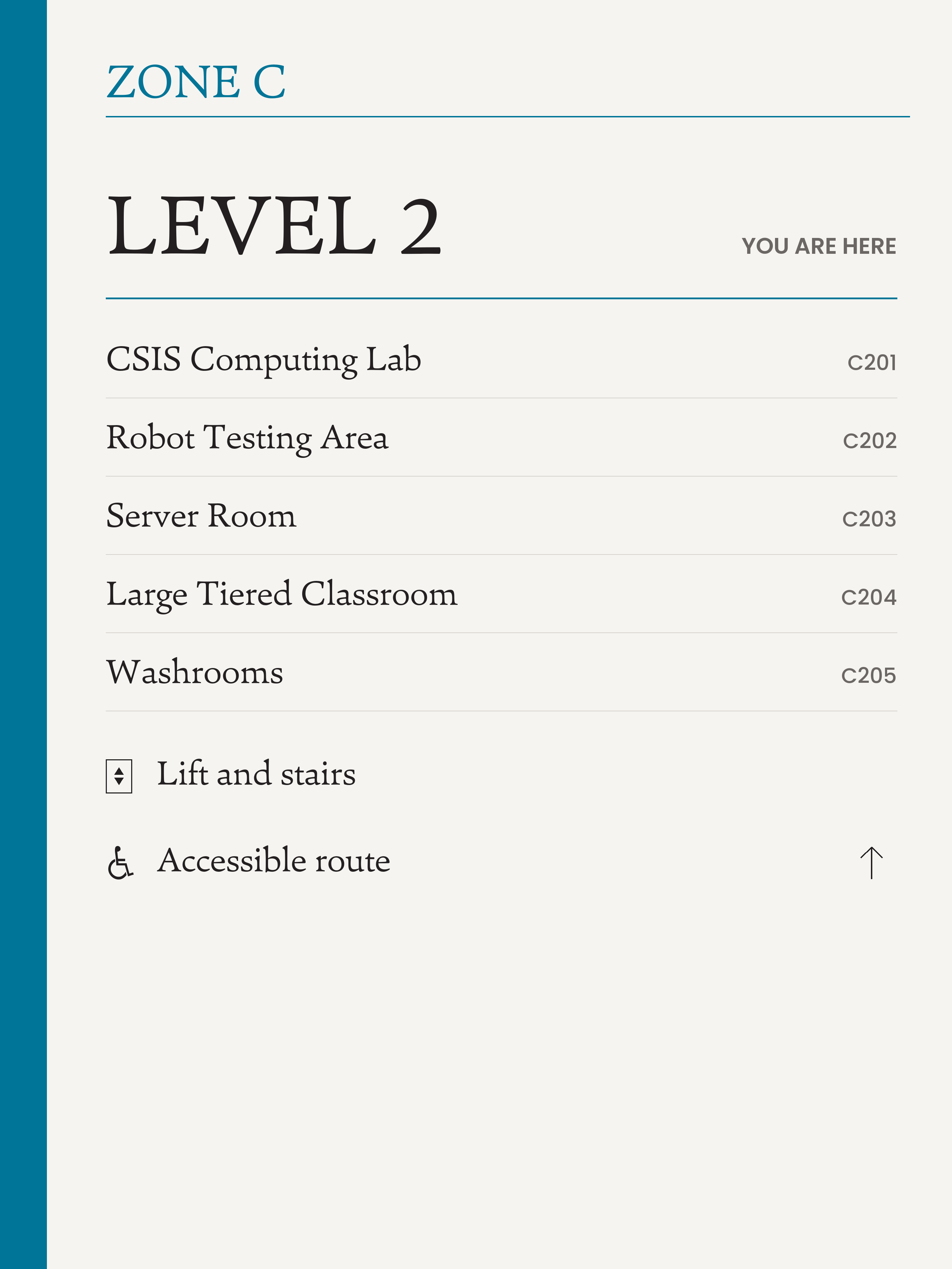
- Size
- 1200 × 1198 mm
- Cap height
- 54 mm level · 25 mm rows · 11 mm references
- Read from
- 5 m rows · 2 m references
One sign doing both jobs. Every row of the level listing carries its own arrow, so the same plate serves a foyer, a lift lobby, a stair head and a corridor decision point — the earlier scheme split this into a directory that listed and a directional that pointed. The core and the accessible route each keep their own line. The plate is sized to the wing’s list rather than trimmed to a fixed height, so Wing D runs 934 mm against 1,198 mm elsewhere.
- Size
- 300 × 300 mm
- Cap height
- 75 mm numeral · 16 mm tactile
- Read from
- 6 m
Drawn at the scheduled 300 mm, so it carries the level and the core and nothing else — the visual numeral above a tactile line repeating it. Which levels a core actually reaches is directory content and belongs on W01, the sign a reader consults before choosing a core; Wing A has no lift at all, so its marker reads Stairs.
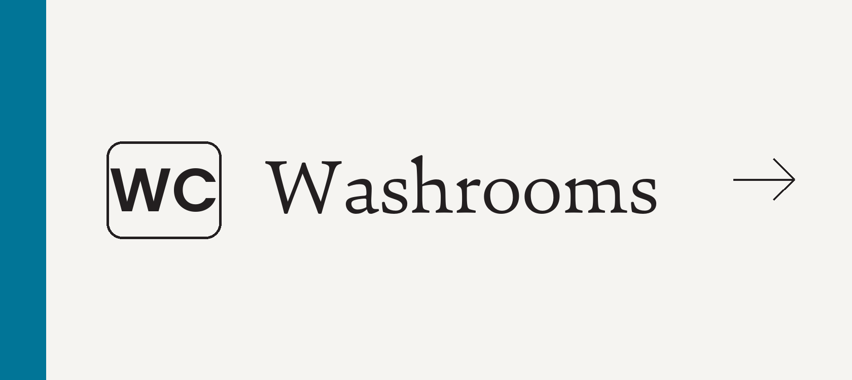
- Size
- 560 × 250 mm
- Cap height
- 34 mm
- Read from
- 5 m
Entirely new. There were 29 washroom door signs in the schedule and nothing that directed anyone to one — washrooms sat as a text row on the floor directory. Ten of these go at corridor decision points, where a reader is furthest from a landing. The WC badge stands in for the supplied ISO 7001 pictogram.
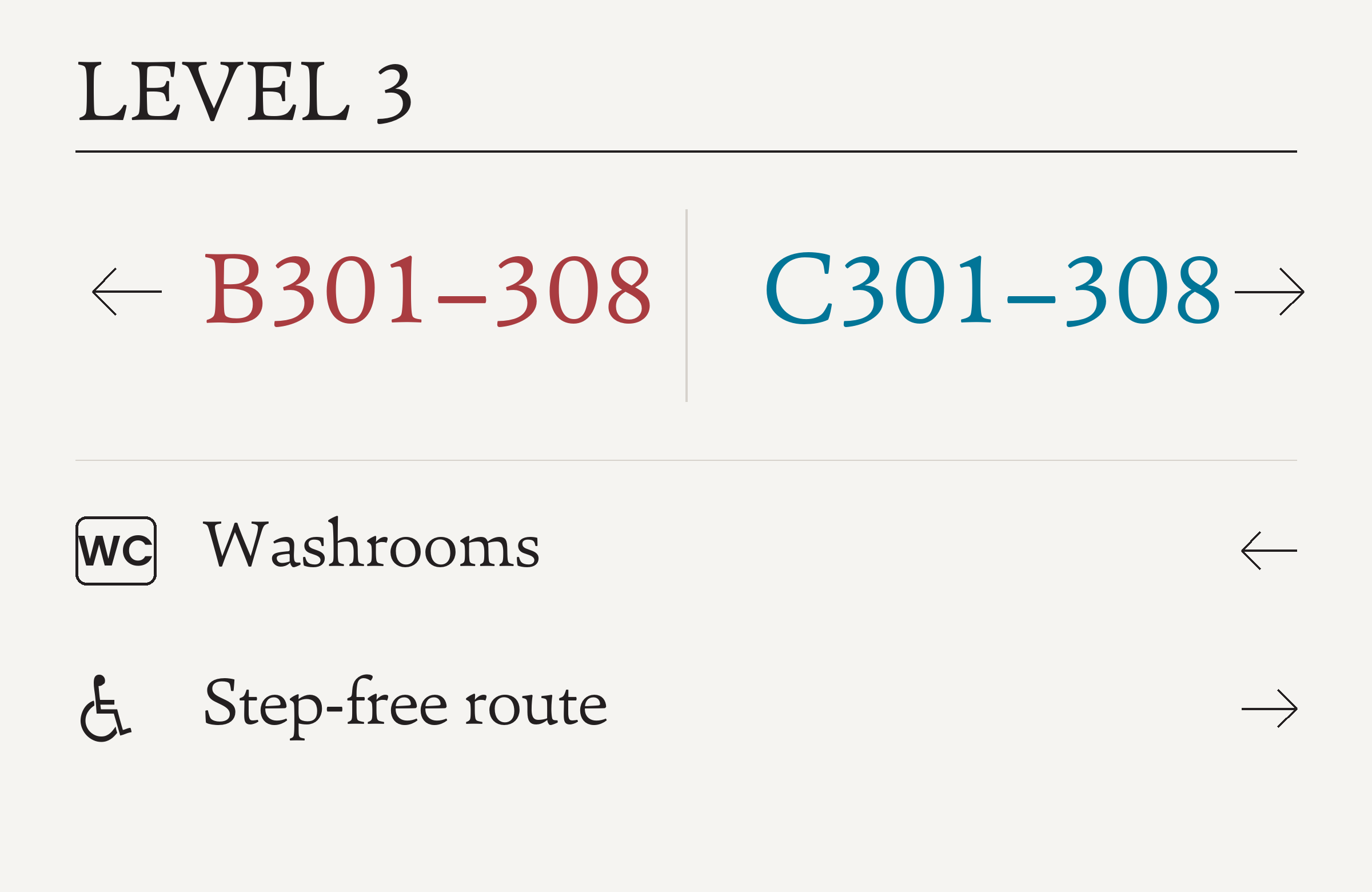
- Size
- 800 × 520 mm
- Cap height
- 40 mm ranges · 34 mm level · 26 mm rows
- Read from
- 5 m ranges
The hotel pattern, at all 24 lift and stair landings. The tactile core marker states the level and stops; this names where each direction leads. It works without renumbering because each wing and level is already a contiguous range.
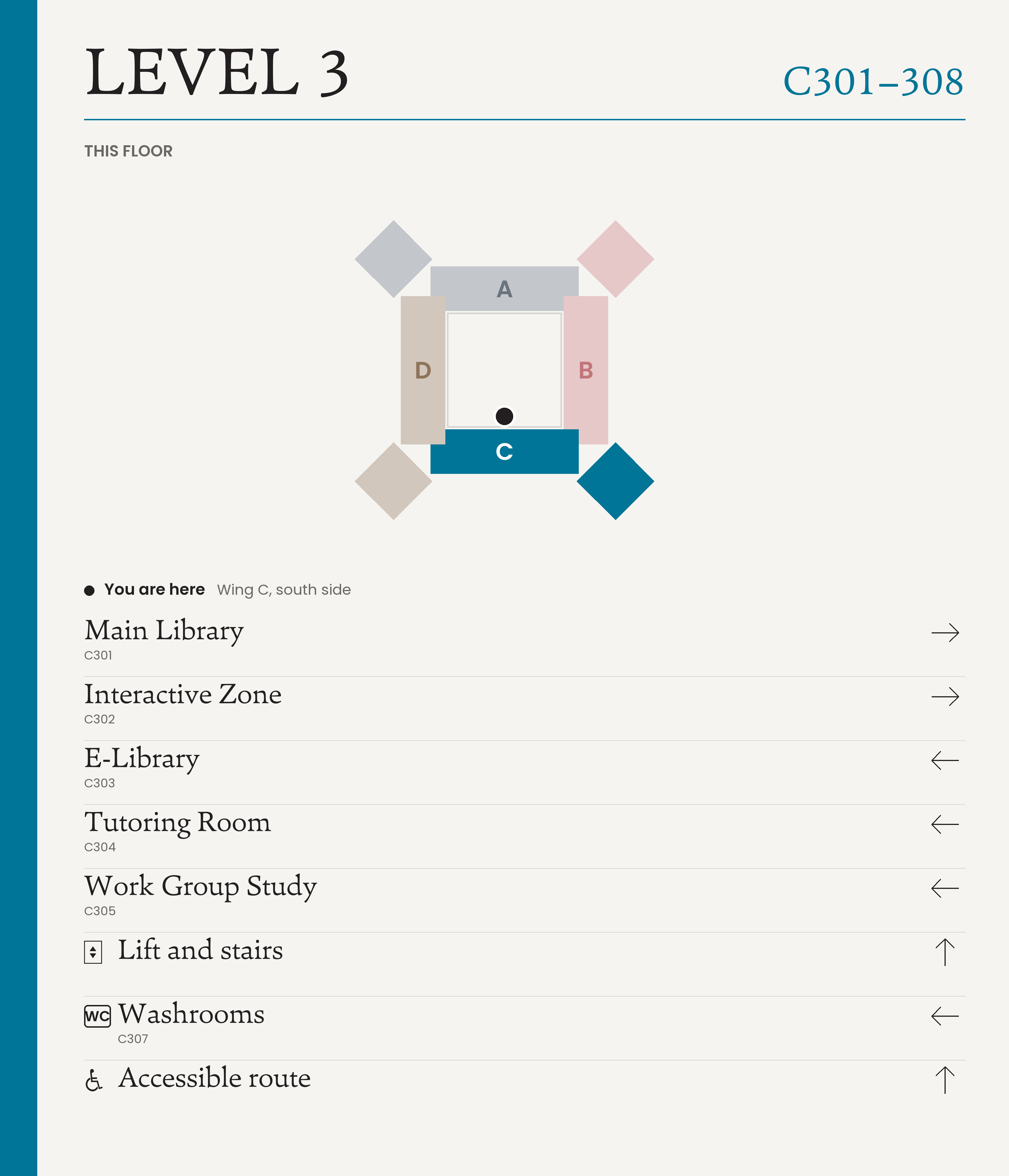
- Size
- 1200 × 1398 mm
- Cap height
- 54 mm level · 23 mm rows · 13 mm plan labels
- Read from
- 5 m rows · 2 m plan
The gateway sign, reworked. Feedback in review was that announcing a wing can confuse rather than orient, so the wing marker becomes optional and this takes the gateway role — a simplified plan of the whole floor with a you-are-here mark, over the destinations on this level. The list is capped at five destinations: the plan does the orienting, and a taller plate would push the top line past the 1600 mm the spec allows for anything that has to be read. None are placed on the plans yet — the schedule will count them as they are added.
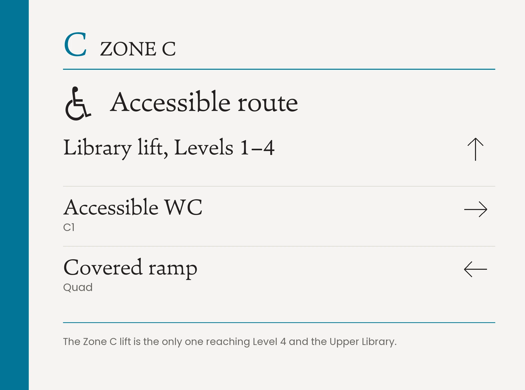
- Size
- 700 × 520 mm
- Cap height
- 25 mm heading · 20 mm destinations
- Read from
- 5 m
The accessible route is stored and signed separately from the direct one. Where a wing cannot provide step-free access itself, the sign says so and routes out of the wing rather than leaving someone to discover it.

- Size
- 360 × 240 mm
- Cap height
- 24 mm number · 14 mm name
- Read from
- 1.5–2 m
The number leads, because it is the permanent estate identifier; the name sits beneath it on the replaceable insert. Renaming a room costs an insert rather than a sign and new wall fixings.
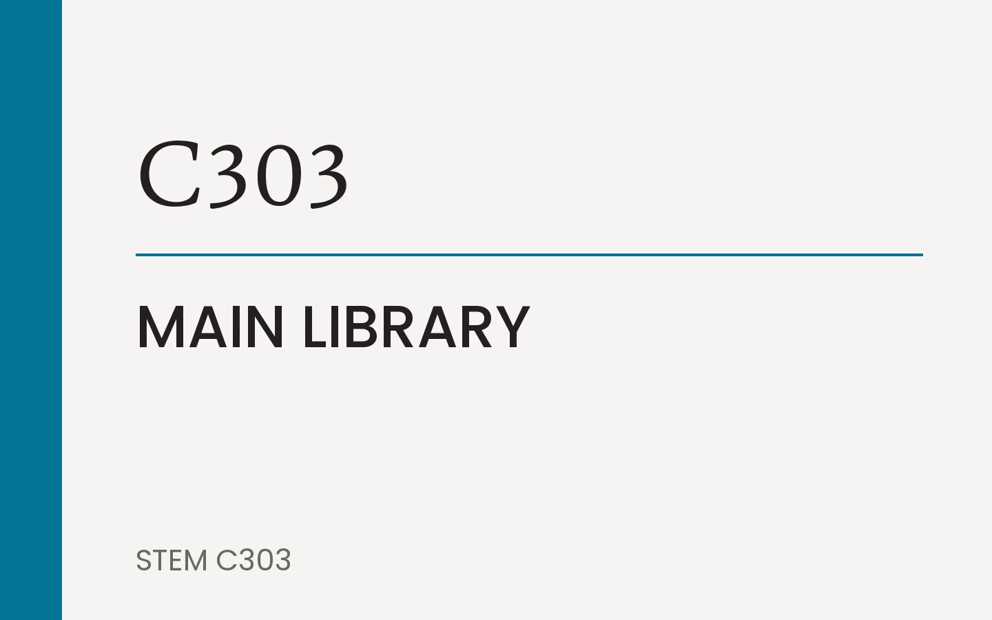
- Size
- 480 × 300 mm
- Cap height
- 30 mm number · 14 mm name
- Read from
- 4 m
The same plate family at a larger module, for departments and open-plan areas that have no single door and are read from further away.
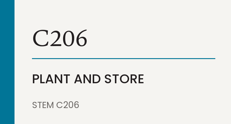
- Size
- 360 × 180 mm
- Cap height
- 20 mm number · 14 mm name
- Read from
- 1.5 m
The smallest plate in the set, for risers, stores and plant. Read at the door and nowhere else, so it carries the reference and nothing more.
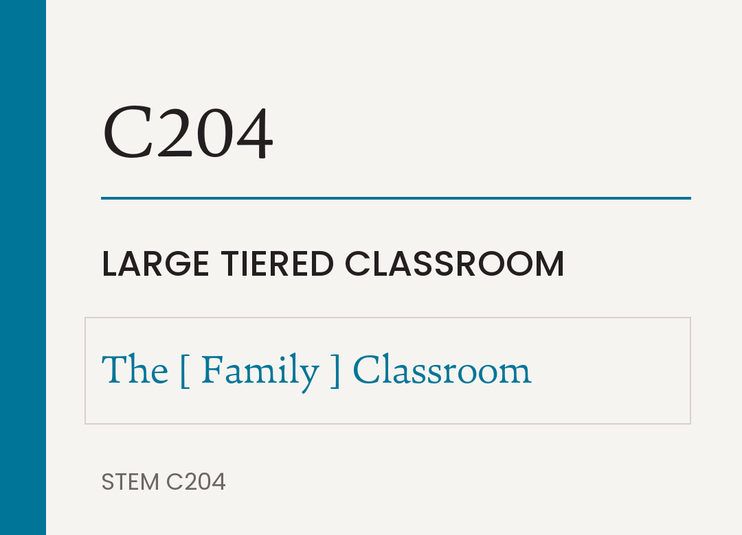
- Size
- 360 × 240 mm
- Cap height
- 24 mm number · 14 mm name
- Read from
- 1.5–2 m
The room sign’s carrier with the naming insert in place of the room’s name: the number, then the named space on two lines — The Ashesi Foundation Classroom. The room’s own name is not repeated. The name shown is a placeholder for the mechanism, not a proposal — naming has not been decided, and nothing in the package waits on it.
Wing D — the full set
Chocolate sits close to Slate in luminance, at 9.13:1. Hue alone does not separate the two, which is exactly why every wing cue names the wing in words as well as carrying its color.
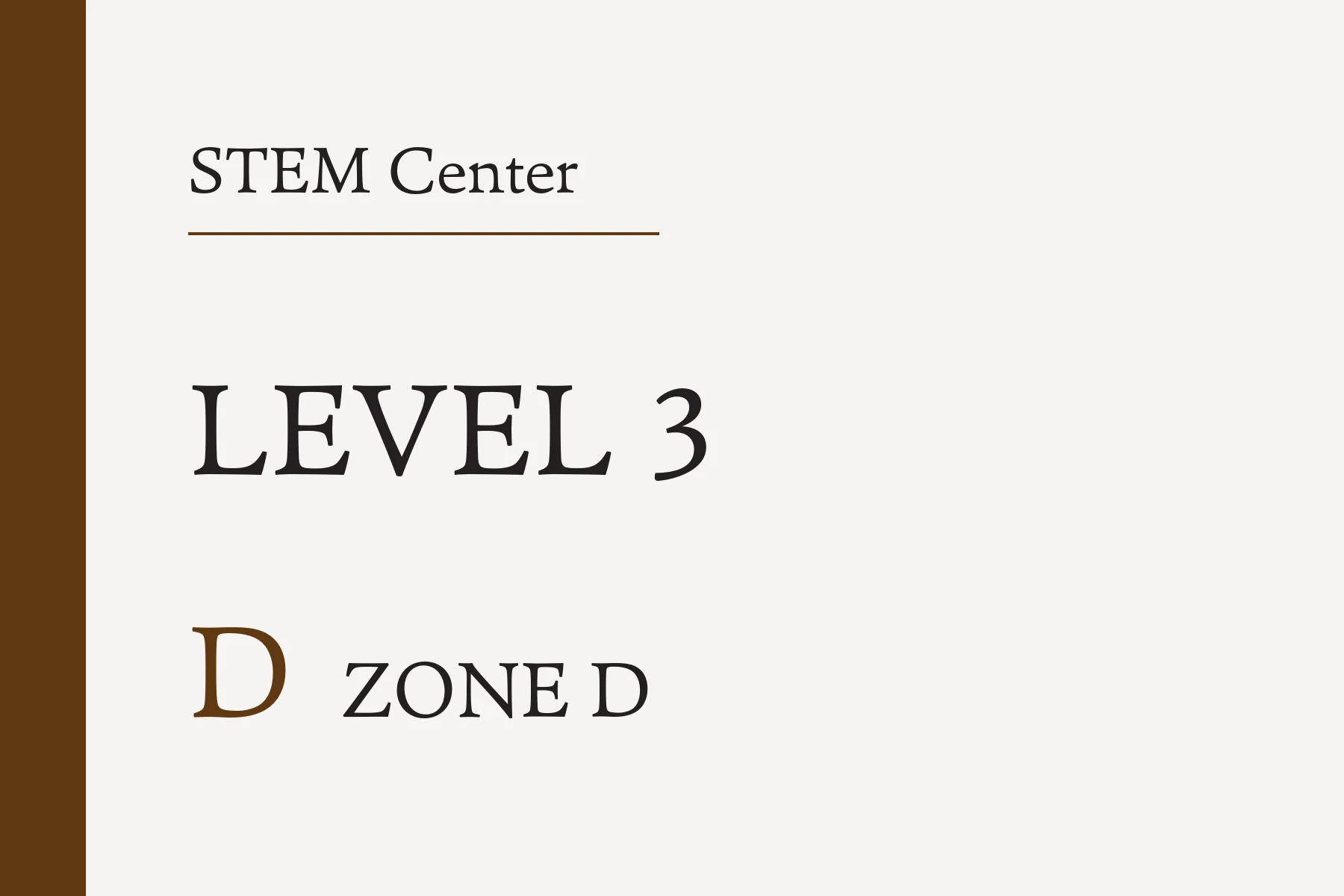
- Size
- 600 × 400 mm
- Cap height
- 40 mm level · 30 mm wing
- Read from
- 8 m
Names the building, the level being entered and the wing you are standing in. Because the site slopes, a visitor can enter directly from outside onto different levels, so every entrance carries one.
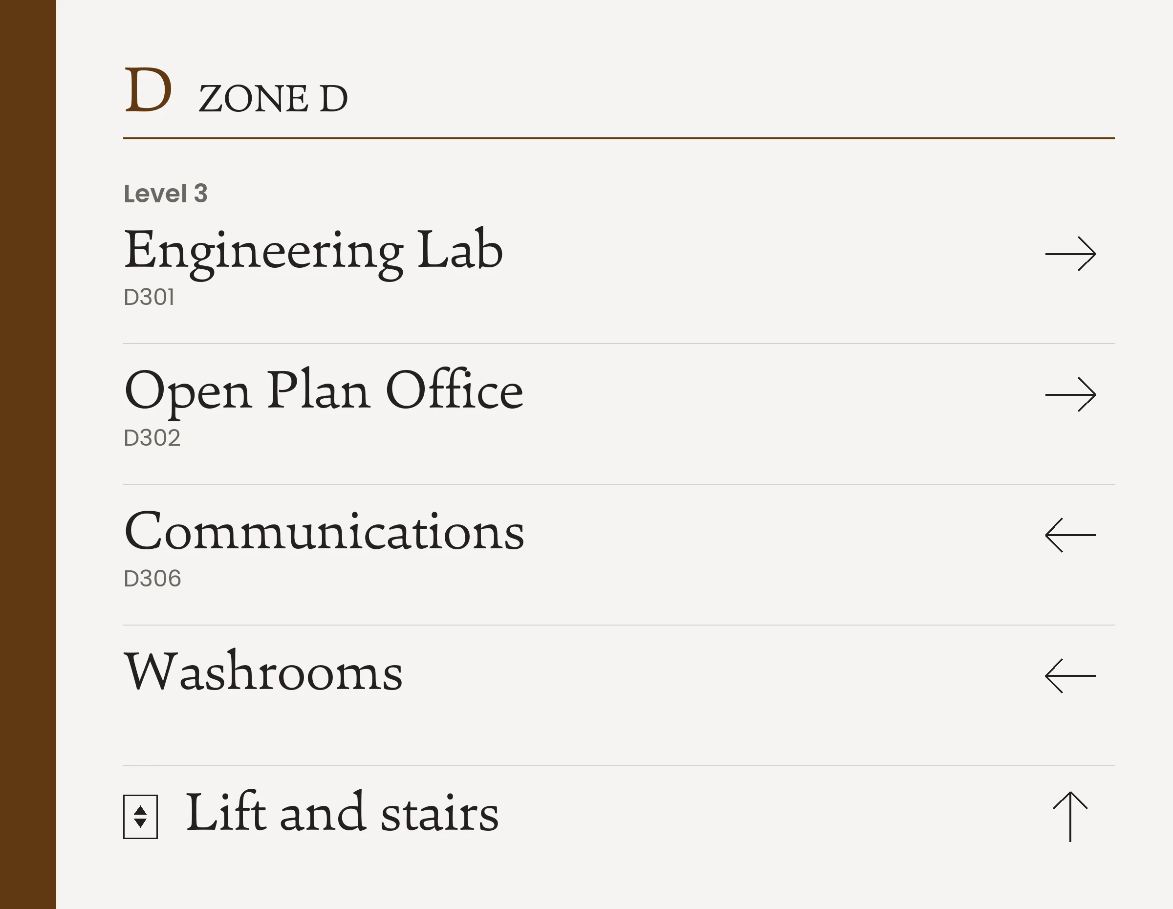
- Size
- 450 × 450 mm
- Cap height
- 165 mm letter · 34 mm label
- Read from
- 8 m label
The one sign that keeps the oversized letter above the label — it is read across a foyer and is what tells someone they have moved between four wings that otherwise look alike. Elsewhere the letter beside the same words only repeats itself, so those signs carry the label alone.
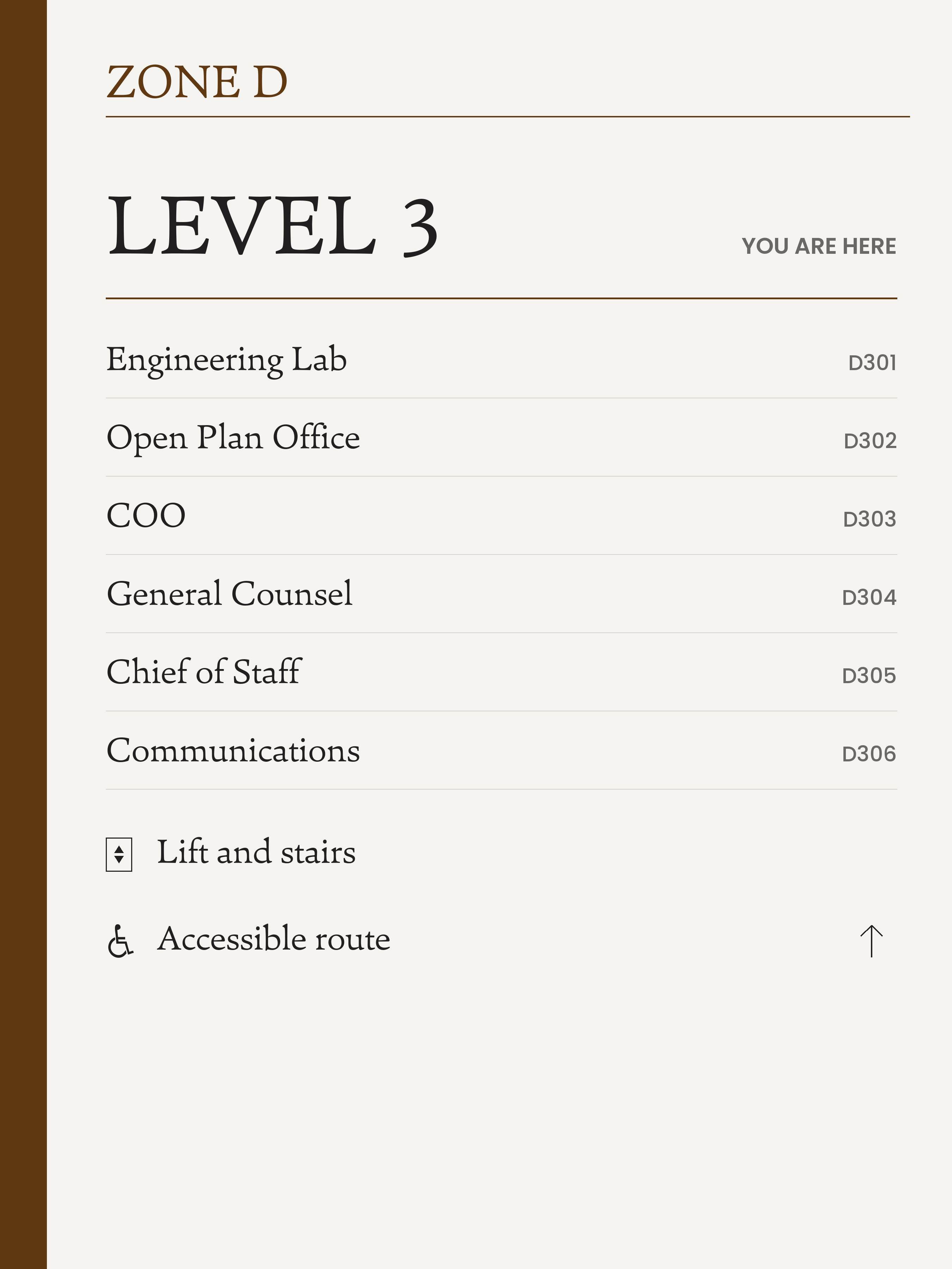
- Size
- 1200 × 1198 mm
- Cap height
- 54 mm level · 25 mm rows · 11 mm references
- Read from
- 5 m rows · 2 m references
One sign doing both jobs. Every row of the level listing carries its own arrow, so the same plate serves a foyer, a lift lobby, a stair head and a corridor decision point — the earlier scheme split this into a directory that listed and a directional that pointed. The core and the accessible route each keep their own line. The plate is sized to the wing’s list rather than trimmed to a fixed height, so Wing D runs 934 mm against 1,198 mm elsewhere.
- Size
- 300 × 300 mm
- Cap height
- 75 mm numeral · 16 mm tactile
- Read from
- 6 m
Drawn at the scheduled 300 mm, so it carries the level and the core and nothing else — the visual numeral above a tactile line repeating it. Which levels a core actually reaches is directory content and belongs on W01, the sign a reader consults before choosing a core; Wing A has no lift at all, so its marker reads Stairs.
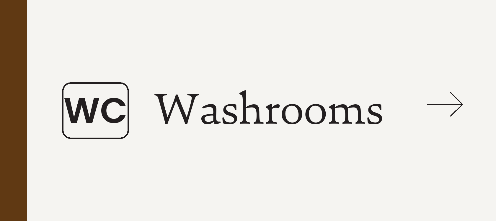
- Size
- 560 × 250 mm
- Cap height
- 34 mm
- Read from
- 5 m
Entirely new. There were 29 washroom door signs in the schedule and nothing that directed anyone to one — washrooms sat as a text row on the floor directory. Ten of these go at corridor decision points, where a reader is furthest from a landing. The WC badge stands in for the supplied ISO 7001 pictogram.
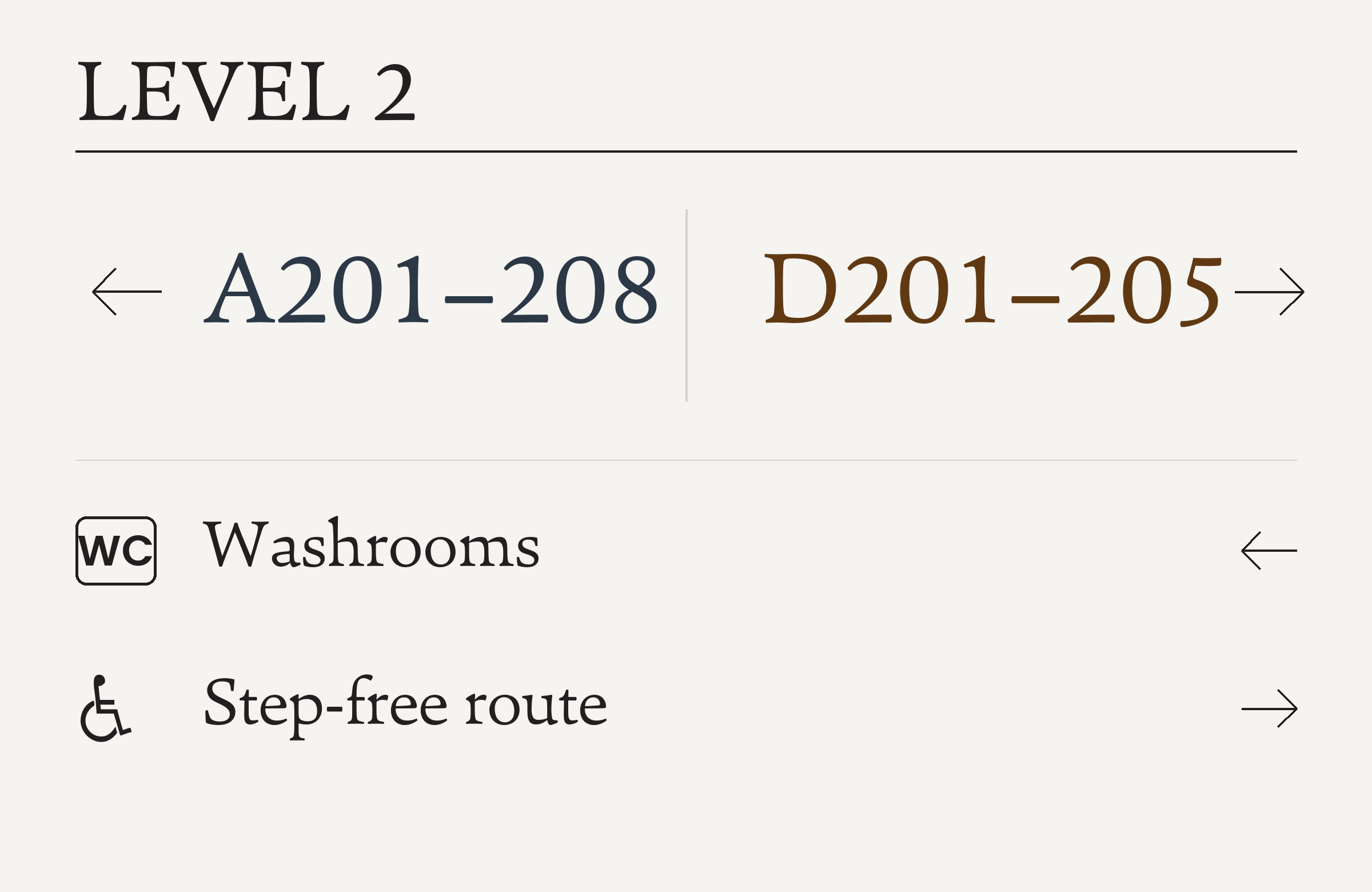
- Size
- 800 × 520 mm
- Cap height
- 40 mm ranges · 34 mm level · 26 mm rows
- Read from
- 5 m ranges
The hotel pattern, at all 24 lift and stair landings. The tactile core marker states the level and stops; this names where each direction leads. It works without renumbering because each wing and level is already a contiguous range.
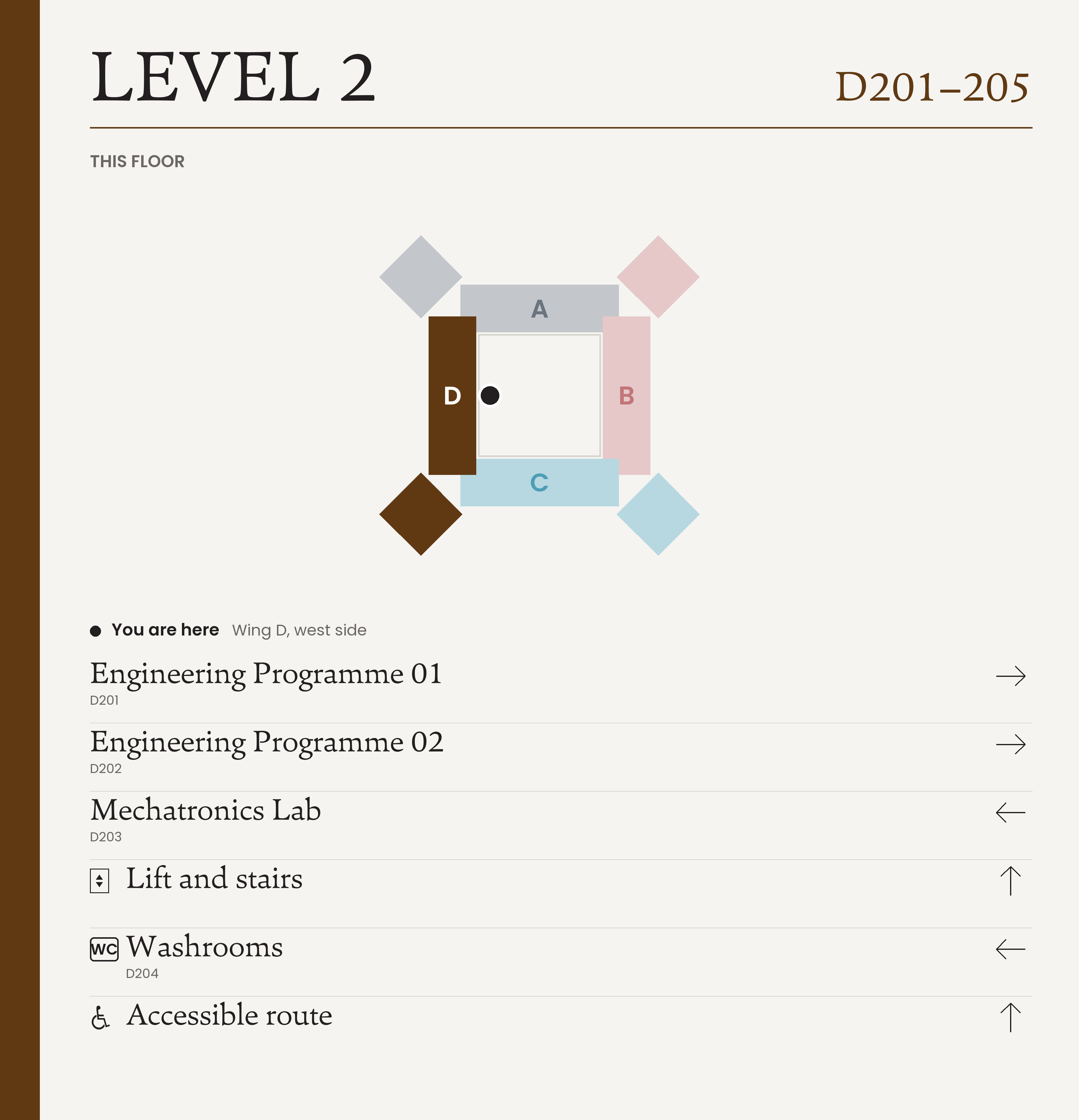
- Size
- 1200 × 1398 mm
- Cap height
- 54 mm level · 23 mm rows · 13 mm plan labels
- Read from
- 5 m rows · 2 m plan
The gateway sign, reworked. Feedback in review was that announcing a wing can confuse rather than orient, so the wing marker becomes optional and this takes the gateway role — a simplified plan of the whole floor with a you-are-here mark, over the destinations on this level. The list is capped at five destinations: the plan does the orienting, and a taller plate would push the top line past the 1600 mm the spec allows for anything that has to be read. None are placed on the plans yet — the schedule will count them as they are added.
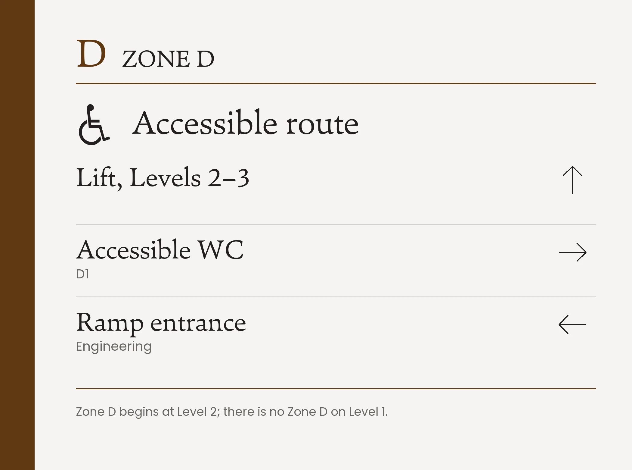
- Size
- 700 × 520 mm
- Cap height
- 25 mm heading · 20 mm destinations
- Read from
- 5 m
The accessible route is stored and signed separately from the direct one. Where a wing cannot provide step-free access itself, the sign says so and routes out of the wing rather than leaving someone to discover it.
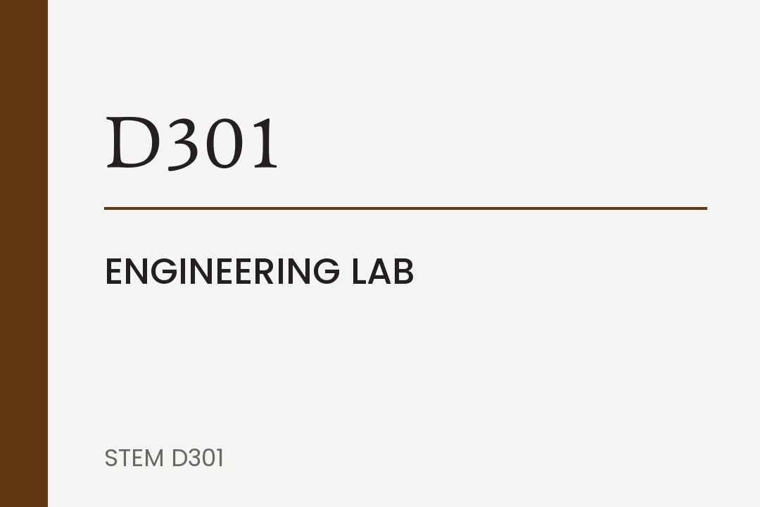
- Size
- 360 × 240 mm
- Cap height
- 24 mm number · 14 mm name
- Read from
- 1.5–2 m
The number leads, because it is the permanent estate identifier; the name sits beneath it on the replaceable insert. Renaming a room costs an insert rather than a sign and new wall fixings.
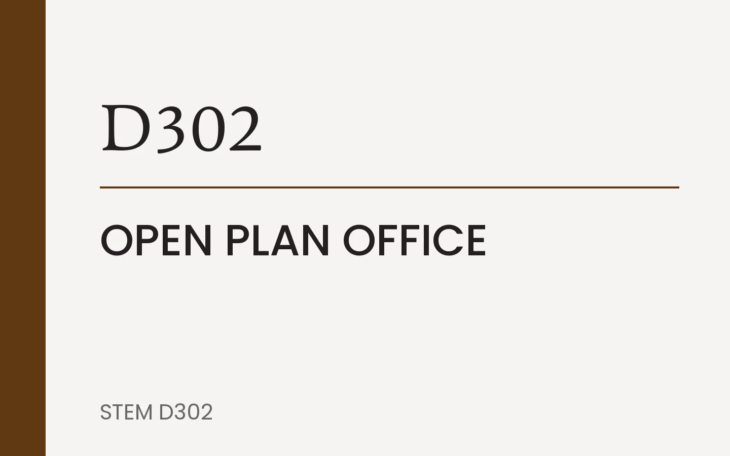
- Size
- 480 × 300 mm
- Cap height
- 30 mm number · 14 mm name
- Read from
- 4 m
The same plate family at a larger module, for departments and open-plan areas that have no single door and are read from further away.
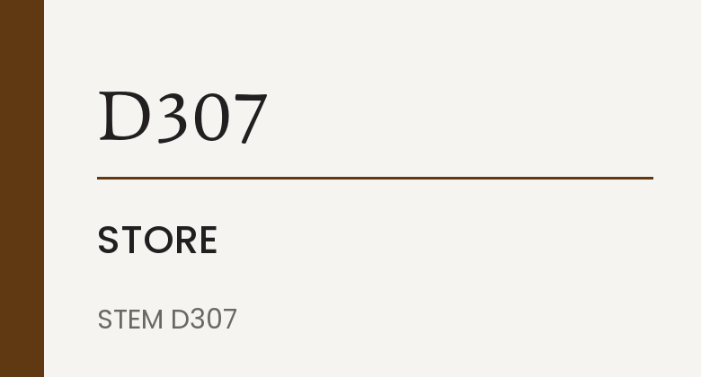
- Size
- 360 × 180 mm
- Cap height
- 20 mm number · 14 mm name
- Read from
- 1.5 m
The smallest plate in the set, for risers, stores and plant. Read at the door and nowhere else, so it carries the reference and nothing more.
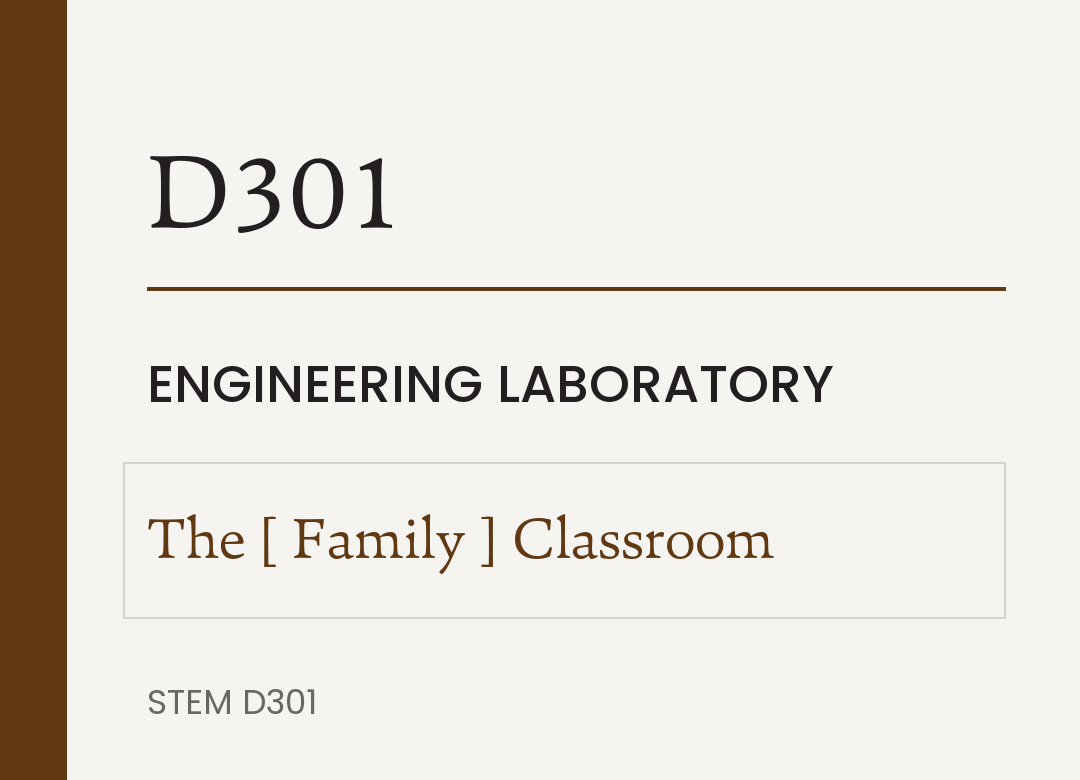
- Size
- 360 × 240 mm
- Cap height
- 24 mm number · 14 mm name
- Read from
- 1.5–2 m
The room sign’s carrier with the naming insert in place of the room’s name: the number, then the named space on two lines — The Ashesi Foundation Classroom. The room’s own name is not repeated. The name shown is a placeholder for the mechanism, not a proposal — naming has not been decided, and nothing in the package waits on it.
Sign schedule and plans
The floor plans and the room schedule behind every sign are both taken from the updated Sutherland & Sutherland set. The site plan is still the 2023 one, because the new set has none. The executive offices moved from Wing D Level 3 to Wing B Level 2, and the Anatomy & Physiology Lab moved the other way. Twenty-five plates for newly drawn offices are placed at estimated positions and are marked as such — they need checking on the plans before fabrication.
The measured positions behind the proposal. Indicative — final quantities need a complete door and GA package.
Open the interactive plans 522 measured positions across the site and Levels 1–4. Identification, regulatory and naming signs group one marker per space; filter by family or type and select any marker for its specification.The tender covers the exterior, wayfinding and identification families — 270 signs. Regulatory and naming signage is held to phase 2 and may be produced in-house, so it is subtotalled separately below and switched off by default on the plans.
522 measured positions, of which map to the proposed type list. The remaining 26 — Vehicular directional (4) and Nook, pod and interactive (22) — have no equivalent in it, and are held rather than reassigned.
| Set | Type | Description | Site | 1 | 2 | 3 | 4 | Total |
|---|---|---|---|---|---|---|---|---|
| E | E01 | Building identification | 3 | — | — | — | — | 3 |
| E02 | Entrance and level sign | — | 4 | 6 | — | — | 10 | |
| E03 | Campus directional | 8 | — | — | — | — | 8 | |
| E2* | Vehicular directional | 4 | — | — | — | — | 4 | |
| W | W01 | Floor directory and directional | — | 12 | 17 | 16 | 2 | 47 |
| W02 | Wing / room-range marker (optional) | — | 3 | 6 | 6 | — | 15 | |
| W03 | Core and level marker | — | 6 | 9 | 7 | 2 | 24 | |
| W04 | Washroom directional | — | 2 | 4 | 4 | — | 10 | |
| W05 | Landing sign | — | 6 | 9 | 7 | 2 | 24 | |
| W06 | Gateway floor directory | — | — | — | — | — | 0 | |
| I | I01 | Standard room sign | — | 27 | 50 | 67 | 4 | 148 |
| I02 | Department sign | — | 3 | 5 | 5 | 1 | 14 | |
| I03 | Technical and service room identification | — | — | — | — | — | 0 | |
| I3* | Nook, pod and interactive | — | 4 | 10 | 8 | — | 22 | |
| For tender — exterior, wayfinding and identification | 15 | 67 | 116 | 120 | 11 | 329 | ||
| R | R01 | Fire and escape information | — | 24 | 44 | 42 | 4 | 114 |
| R02 | Laboratory hazard and PPE | — | 6 | 17 | 16 | — | 39 | |
| R03 | Restricted access | — | 5 | 10 | 6 | 2 | 23 | |
| R04 | Accessibility information | — | 4 | 8 | 7 | 1 | 20 | |
| N | N01 | Named spaces | — | 6 | 15 | 17 | 2 | 40 |
| N02 | Donor recognition | — | 1 | — | 1 | — | 2 | |
| N03 | Dedications | — | — | 2 | — | — | 2 | |
| N04 | Interpretive content | — | 3 | 5 | 3 | 1 | 12 | |
| Phase 2 — regulatory and naming | — | 49 | 101 | 92 | 10 | 252 | ||
| Total measured | 15 | 116 | 217 | 212 | 21 | 581 | ||
Generated from the same marker data that drives the plans, so the schedule and the drawings cannot disagree. Rows in a lighter tone carry a provisional code.
Type specification
EExterior & Site
Building identification
3 indicativeIdentifies the building at the vehicular approach and on the pedestrian frontage.
- Size
- 2000 × 480 mm plate, in a 2.7–3.0 m installation
- Mounting
- Wall
- Read from
- 30 m
- Cap height
- 150 mm
Entrance and level sign
10 indicativeNames the building, states the level being entered and the wing you are standing in. Every significant entrance carries one.
- Size
- 600 × 400 mm
- Mounting
- Wall
- Read from
- 8 m
- Cap height
- 40 mm level · 30 mm wing
Campus directional
8 indicativeHands the visitor off to wider campus destinations.
- Size
- 700 × 520 mm
- Mounting
- Wall or post
- Read from
- 5 m
- Cap height
- 25 mm
Vehicular directional
4 indicativeFour Revision 02 positions with no equivalent in the proposed exterior list. Held pending a decision on whether vehicular routing stays in this package.
- Size
- To be confirmed
- Mounting
- Post-mounted (Rev 02)
- Read from
- 12 m
- Cap height
- 60 mm (Rev 02)
WWayfinding
Floor directory and directional
47 indicativeOne sign for both jobs: the full listing for a level of a wing, with an arrow on every row. Works at a foyer, a lift lobby, a stair head or a corridor decision point. The core and the accessible route each get their own line.
- Size
- 1200 × 934–1198 mm, sized to the wing’s list
- Mounting
- Wall
- Read from
- 5 m rows · 2 m references
- Cap height
- 54 mm level · 25 mm rows · 11 mm references
Wing / room-range marker (optional)
15 indicativeOptional. Review feedback was that a sign announcing a wing can confuse rather than orient, so the gateway role passes to W06 and this is specified only where a foyer needs a landmark read across the space. Marks a wing and does real navigational work: the room ranges and key destinations reached in each direction, with the wing letter and color as reinforcement — not a standalone announcement of an abstract zone.
- Size
- 450 × 450 mm interior · 900 × 900 mm courtyard
- Mounting
- Wall or column
- Read from
- 8 m label
- Cap height
- 165 mm letter · 34 mm label
Core and level marker
24 indicativeStates the level and which core you are standing at, visually and in tactile form on the landing.
- Size
- 300 × 300 mm
- Mounting
- Facing landing at 1500 mm; tactile 1200–1500 mm
- Read from
- 6 m
- Cap height
- 75 mm numeral · 16 mm tactile
Washroom directional
10 indicativeDirects to the nearest washrooms from a corridor decision point. The set identified washrooms at the door but never pointed at one.
- Size
- 560 × 250 mm
- Mounting
- Wall or suspended
- Read from
- 5 m
- Cap height
- 34 mm
Landing sign
24 indicativeRoom-number ranges split at a lift or stair landing, with the washroom and step-free route beneath. Carries destinations, which the 300 mm tactile core marker cannot.
- Size
- 800 × 520 mm
- Mounting
- Facing the landing at 1500 mm
- Read from
- 5 m ranges
- Cap height
- 40 mm ranges · 34 mm level · 26 mm rows
Gateway floor directory
0 indicativeThe arrival board at a wing threshold, and the gateway sign in place of W02. A simplified plan of the whole floor with a you-are-here mark, over the destinations on this level. It says where you are standing rather than announcing which wing you have entered.
- Size
- 1200 × 1246–1398 mm, sized to the wing’s list
- Mounting
- Wall, centre 1500 mm
- Read from
- 5 m rows · 2 m plan
- Cap height
- 54 mm level · 23 mm rows · 13 mm plan labels
IIdentification
Standard room sign
148 indicativeThe permanent number leads; the name sits beneath it on the replaceable insert, with the campus reference below.
- Size
- 360 × 240 mm
- Mounting
- Wall, latch side
- Read from
- 1.5–2 m
- Cap height
- 24 mm number · 14 mm name
Department sign
14 indicativeThe same plate family at a larger module, for departments and open-plan areas with no single door.
- Size
- 480 × 300 mm
- Mounting
- Wall
- Read from
- 4 m
- Cap height
- 30 mm number · 14 mm name
Technical and service room identification
0 indicativePlant, store, riser and technical spaces.
- Size
- 360 × 180 mm
- Mounting
- Wall or door leaf
- Read from
- 1.5 m
- Cap height
- 20 mm number · 14 mm name
Nook, pod and interactive
22 indicativeTwenty-two Revision 02 positions with no equivalent in the proposed identification list. Held pending a decision on whether pods are separately identified.
- Size
- To be confirmed
- Mounting
- Wall or furniture (Rev 02)
- Read from
- 1.5 m
- Cap height
- 16 mm (Rev 02)
RRegulatory & Safety
Fire and escape information
114 indicativeEscape routes, final exits, fire action notices and equipment.
- Size
- Per ISO 7010 / ISO 16069
- Mounting
- Wall
- Read from
- Per standard
- Cap height
- Per standard
- Standard
- Statutory safety colors and symbols govern
Laboratory hazard and PPE
39 indicativeHazard identification, mandatory PPE and emergency equipment.
- Size
- Per ISO 7010 · GHS
- Mounting
- Wall
- Read from
- 1.5–2 m
- Cap height
- Per standard
- Standard
- ISO 7010 · GHS
Restricted access
23 indicativeAuthorized access only at plant, server, tank and technical spaces.
- Size
- Per ISO 7010
- Mounting
- Wall or door leaf
- Read from
- 1.5 m
- Cap height
- Per standard
- Standard
- ISO 7010
Accessibility information
20 indicativeAccessible route marking, accessible WC identification and assistance instructions.
- Size
- 700 × 520 mm
- Mounting
- Wall
- Read from
- 5 m
- Cap height
- 25 mm heading · 20 mm destinations
- Standard
- Act 715 · ISO 21542
NNaming & Recognition
Named spaces
40 indicativeThe room sign’s carrier, with the name on its insert in place of the room’s own name.
- Size
- 360 × 240 mm
- Mounting
- Wall
- Read from
- 1.5–2 m
- Cap height
- 24 mm number · 14 mm name
Donor recognition
2 indicativeModular panels on a fixed rail.
- Size
- Modular
- Mounting
- Wall
- Read from
- 2–3 m
- Cap height
- Varies
Dedications
2 indicativePermanent, single-issue.
- Size
- Single-issue
- Mounting
- Wall
- Read from
- 1.5 m
- Cap height
- Varies
Interpretive content
12 indicativeStory and interpretive graphics.
- Size
- Varies
- Mounting
- Wall
- Read from
- 1.5–3 m
- Cap height
- Varies
Decisions for this review
The seven decisions that define the system. Please confirm:
Approve Levels 0–4 as the public level names. Architectural terms stay in coordination use only.
Approve STEM C201 as the campus-wide format — Building + Wing + Level + Room.
Approve A–D as addressing and spatial identifiers rather than primary visitor destinations.
Approve A · Slate, B · Ashesi Red, C · Turquoise, D · Chocolate — white type on all four.
Approve navigation led by destinations, essential services and room ranges, with wing color as reinforcement.
Approve wall-mounted internal wayfinding as the design basis.
Approve the preferred visual treatment to take forward into detailed development.
To settle with the drawings and the register
Confirm whether the August 2026 set is “for construction” or “for client approval”. The title blocks and the sheet annotations disagree, and the revision tables are empty. The Lower Ground, Ground and First Floor sheets also all carry the same sheet number, C-202. Everything here is calibrated against those drawings.
Confirm whether Facilities or the Registry owns room numbering, and whether an existing campus convention must be inherited. A fabricator cannot price door plates until this is settled.
The tender sheet carries a 900 × 250 mm suspended directional. Carrying the room ranges and the floor list needs about 1200 × 1198 mm. It affects 47 signs.
Twenty-five room plates for newly drawn offices are placed at estimated positions and need checking on the plans before fabrication.